
These suggestions and solutions for technical problems come from service bulletins published by Daimler-Benz, selected and rewritten for independent repair shops.
Restart delay relay
Models 201, 124 and 126
To prevent clash between the starter drive and the ring gear/flexplate teeth, many but not all models 201, 124 and 125, beginning in 1989, have a timer relay that prevents a second cranking attempt for a period of two seconds after one that fails to start the engine. The purpose is to allow the crankshaft to come to a complete stop before the starter drive re-engages the ring gear/flexplate teeth. OK, so far so good. But here’s the problem: If the relay fails, you can get another relay from your Mercedes-Benz parts supplier. If the harness fails, however, you must either repair the harness, or if that proves impossible for some reason, you must wire around the relay. There is no replacement harness.
First, confirm that you have a car with the crank-delay relay. In each of these line drawings, it is relay N38.
If you want more detail on how to wire around the relay, see Electrical Troubleshooting Manual, p. 113 model 124, p. 105 model 126.
MBNA 15/45
 Moisture in fuse and relay box
Model 124
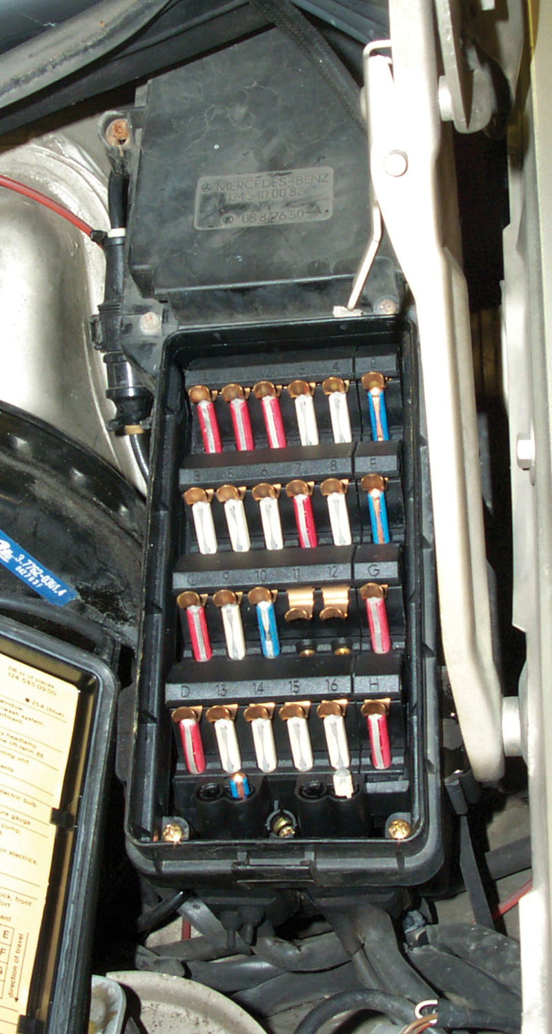
A leak in the fuse box lid or through the rubber boot around it may allow moisture to collect in the fuse box, a condition that could eventually lead to corrosion and harness component failure. If you find a car with that condition, first remove the fuse and relay carrier and dry all the components and the fuse box. Replace any parts damaged by the water. Then drill a 6 mm hole in the place indicated in the illustration, the lowest point in the fuse box [P00.00-1072-01 or photograph]. Check the fuse box cover and the gasket and seal all the rubber boots on the box for leaks with sealing compound as needed.
AF00.00-U-4040AU
Central locking system does not work below freezing
All models
Moisture is getting into the system through one or more leaking elements and then forming a pneumatic block when it turns to ice with the cold. First perform vacuum and pressure leak tests to locate and repair the leaks by replacing the defective components. Then blow out all the lines individually with dry compressed air or a commercial nitrogen gas drier. Remove any working elements with water in them from the vehicle, turn them upside down and actuate each about five times. Shake all the remaining water out and repeat the process until they’re completely dry.
AF80.20-U-4010A
Mercedes-Benz Service Information Website
Mercedes-Benz is committed to keeping you informed as we move forward in the Information Age. That’s why we are happy to announce a planned Mercedes-Benz website jam-packed with service information, technical data and much more, all accessible by members of the independent vehicle repair industry.
So stay tuned with StarTuned, your Mercedes-Benz technical and parts information connection.
Cylinder head bolt notes
All models
Everyone knows not to use impact wrenches to tighten cylinder head bolts, but on Mercedes-Benz engines don’t use them to remove the bolts, either, to protect the threads in the block. Many engines are aluminum or other thinwall castings, so it is also critical to insure the boltholes are completely emptied of oil and antifreeze before head bolts are re-installed. Blowing such residue out with compressed air is usually a satisfactory technique, but inspect each hole to confirm removal of any dirt or liquid. If fluids are left at the bottom of the bore, tightening the bolt could create enough hydraulic pressure to crack the block.
MBNA 01/6
Overrevving damage to torque converter
All models with automatic transmissions
Running an engine beyond redline can damage the engine by floating or bending valves, twisting connecting rods and other equally dire consequences. To prevent that, Mercedes-Benz engines have included maximum engine speed limiters for many years. Those protective measures, however, can only prevent redlining the engine using the throttle. If a driver manually downshifts the transmission at too high a speed, this could result in the vehicle’s momentum spinning the crankshaft above a safe speed.
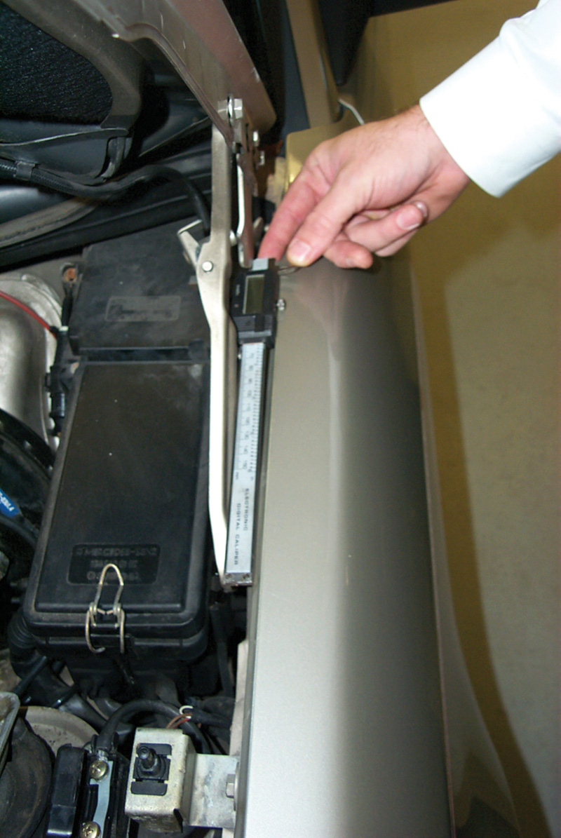
Besides the damage to the engine potentially resulting from a speed above redline, the torque converter can also distort by centrifugal force acting on the transmission fluid in the converter, ‘ballooning’ the converter up. The distortion takes the form of thickening the torque converter, this making it interfere with the front transmission pump and damage the front seal. If an engine has sustained overrevving damage, check the torque converter by placing it on a flat surface with the pump-drive side down. Measure the thickness from the surface to the attachment bolt surface as shown in the illustration [p27-2371-13]. As long as the thickness is 121.5 mm or less, the torque converter is satisfactory; if it is thicker than 121.5 mm, replace the converter.
MBNA 27/82
Oxygen sensors
All models
If an oxygen sensor doesn’t send a proper cycling signal or the vehicle’s self-diagnostic memory records an oxygen sensor fault, confirm that the oxygen sensor is properly grounded before you replace it. Not only must the sensor make a secure electrical connection to the exhaust system; the exhaust system must also make a secure electrical connection through the engine cylinder head to the negative terminal of the battery. Confirm also that the computer shares the same ground as the oxygen sensor does. Only if the groundside of the circuit is good but you don’t find a signal from the sensor, should you replace the sensor.
MBNA 07.3/11
EGR functional test
All models with EGR
Everybody knows that the diaphragm on an EGR valve must hold vacuum built with a hand pump or else the valve is defective, but you’d like to know the valve works actively as well. Once you’ve confirmed the diaphragm is intact, release the vacuum suddenly. If the valve works as it is supposed to, you’ll hear an audible pop from the valve as the pintle snaps closed.
MBNA 14/6
 Hood hinge test
All models
Here’s a quick and accurate test to see whether a hood hinge has been damaged on a Mercedes-Benz vehicle: Place a short (150 mm) ruler or straightedge against the outside surface of the hinge, with the hood at the 45-degree position. If the gap between the hinge and your straightedge is 0.0 to 0.2 mm or less, the hinge is good. If the gap is greater, the hinge is bent.
MBNA 88/32
Too clean for safety
All models
Keeping a car clean and polished not only makes it easier on the eye and a source of greater satisfaction for the owner; it also helps prevent rust and abrasion to the paint and other surfaces. But some people get carried away with vehicular tidiness. If you use a pressure washer to clean the wheels and tires, use only a wide, fan-shaped nozzle and keep the tip of the tool constantly moving and at least 12 inches from the tire. A round or pencil blast nozzle can cause pinpoint overheating of the sidewall rubber from high-speed vibration, causing hardening and damage that will not appear until later. Such a nozzle can cause invisible tire damage even at a distance of 30 inches. And a sidewall blowout is not something tidy!
MBNA 40/99
 Steering idler freeplay
Models 124, 126, 129 and 201
You should only replace steering linkage idler gear rubber bushings under one of two conditions:
- The bushings are making noise when you turn the steering from lock to lock.
- The total freeplay in the idler arm is more than 0.5 mm as measured at the point where the tie rod connects to the outer end of the idler arm. Use a suitable clamp-on dial indicator to make the measurement.
MBNA 46/72
Engine shuts off, can’t restart Vehicles with gasoline engines
It is possible for the oxygen sensor signal wire to rub against the driveshaft on some Mercedes-Benz vehicles. If the spinning driveshaft wears through the insulation on the wire, this can damage the oxygen sensor and short the printed circuit in the fuel pump relay. Repair requires replacement both of the sensor and the relay. Be sure to route the sensor wire so the problem cannot recur.
07.3-88041
No start
Engines 102 and 103
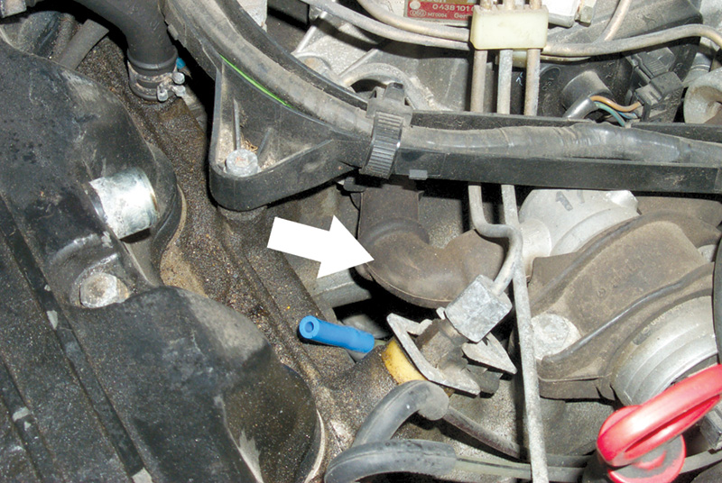
Add to your no-start checks this one: If there was a backfire the last time the engine was running, it is possible the molded hose at the idle air valve (above) fell off, allowing excessive unmeasured air into the intake manifold. While you’re inspecting that hose, confirm that it does not have damage from being swollen or cracked.
07.3-90011
Panel bulb breaks speedo cable? Models 124 and 201
It’s not a very plausible claim, is it? But any attempt to remove the instrument panel, even partially, can damage the accelerator cable, even if you’re just tilting it enough to reach in and swap a burned-out indicator bulb. Before you pull the instrument panel loose, disconnect the speedometer from behind. You don’t want to have to try to explain how the burned out bulb broke the speedometer cable!
MBNA 54/58
Trunk hard to close in winter
Model 201
If it becomes difficult to close the trunk lid on a Model 210 during very cold weather, inspect the condition of the two rubber bumpers at the trunk latch. The rubber bumpers can become very hard at low temperatures, making the trunk difficult to close. Just remove one of the rubber trunk latch bumpers to reduce the problem by exactly half!
AF88.50-U-60001A
Headliner removal/replacement
Model 124
The traditional way to remove a car’s headliner is through the rear window, or ‘backlight.’ The one-piece headliner installed in the M-B 124 from January 1991 on comes out the front passenger door, instead. Here’s how:
- Remove the door frame protection edge from all four doors.
- Remove the windshield moldings from the A-pillars.
- Remove the roof frame panel trim above the windshield.
- Remove the trim panels from the B-pillars.
- Remove the trim panels from the C-pillars.
- Remove the rear interior lamp and assist handles above the doors.
- Move the front seats to their rearmost position and lower the backrests completely.
- Put the gear selector lever in Park.
- Slide the headliner rearward and unhook it from the roof frame. There are two retaining clips.
- Remove the headliner through the front passenger door.
SI 68/18 March 1991
Wood console removal
Model 129
You really, really don’t want to damage the wood paneling on M-B consoles and dashboards because they actually are wood, all from the same tree for a given car. The likelihood of finding a panel that will match exactly is exactly zilch. This means it’s important to use the proper techniques when removing these panels. We’ll fill you in on them in future issues. Here’s how to remove the center console of the Model 129 without putting yourself in the market for some very expensive lumber:
With the ignition off and the parking brake applied, pull the radio using the radio removal keys. Disconnect the electrical connectors.
Reach through the radio opening and push the climate control pushbutton unit outward. Disconnect its electrical connectors.
With an automatic transmission, remove the plastic trim ring around the selector lever and move the lever to position 2. With a manual transmission, disengage the bottom of the shift boot and move the lever into a rearward gate position such as third gear.
Remove the screw in the center of the storage compartment. Bend the upper corners of the storage compartment inward (arrows) and press the compartment forward, removing it by the corners. Don’t use a sharp edged tool when removing the compartment to avoid damaging the wooden cover. Lift the cover only with a small removal hook on the screw hole of the compartment housing.
Remove screws 2 and 3 below the storage compartment.
Press the rear of the console wooden cover left to disengage the catch and lift the right side. Press the rear right to disengage the catch and lift the left side. Lift the rear cover and pull downward out of the upper catches.
Disconnect the wiring connectors from the switches.
Remove the wooden cover.
When reassembling everything, check that all the switches and components work. You’ll have to recode the radio.
MBNA 68/4
Convertible top care and neglect
All models with soft top
Here are a few useful rules for M-B soft top owners:
- Never take the car through an automatic car wash. Never use high-pressure cleaning equipment to wash the soft top.
- Remove all bird droppings immediately. Acids can quickly damage both soft-top material and even body paint.
- Never use ice or snow scrapers or other tools with sharp edges.
- Normally just rinse the soft top with water. Wash it only if it is “significantly” dirty.
- Do not use gasoline, thinners, tar removers, stain removers or other organic solvents when cleaning the soft top.
If the soft top must be cleaned, do the following:
- Clean the top only when it is closed and locked.
- Sweep the soft top with a soft brush while dry.
- Mask all adjacent paint and glass surfaces, including plastic windows.
- Wash with a generous amount of lukewarm water and a neutral detergent.
- Always brush or sponge in the same direction, front to rear.
- Use detergent concentrate only on extremely dirty areas or white/grey patches where there has been contact or chafing.
- Thoroughly rinse with clean water.
- Let the soft top dry completely before putting it down.
MBNA 77/37
Soft top control modules
Models 124 and 129
It may sometimes happen that soft top control modules fail and must be replaced. But this is not the case, in general, with modules that have various DTC’s stored in memory, DTC’s that suspend operation of the soft top. DTC’s that can have this effect are:
- DTC’s 3, 18, 20-24
- DTC’s 21,22, 26, 30
Before replacing a soft top control module, always record what is in fault memory, erase the memory, test drive the vehicle for more than 10 seconds, open and close the soft top. Then read out the DTC memory again.
If there is a problem during soft top operation, hold the switch until the indicator lamp begins blinking. If the previous DTC’s can be erased, soft top operation is possible; that is, the fault is no longer present. DTC 30, however, can be stored again while driving.
MBNA 77/9
Window adjustment
Model 129
Air and water leaks around the windows can often be corrected by readjusting the position of the windows in the doors. Install the hardtop to provide a fixed surface to adjust the window to. Then remove the inner door panel, the lower body protection panel and the speaker group and air passage. Remove the protective plastic liner from the door as well as the inner and outer sealing rail. If the door is not perfectly square in its frame, adjust the door so it is in the correct position.
That done, loosen the guide piece screw and push it downward. Remove the rubber plugs and loosen both 13 mm nuts. Turn the 5.5 mm adjustment bolts so the screws of the guide rail are in the middle of the bracket.
Adjust the window with the front and rear sliding blocks so the window rests parallel and in the middle of the window channel in the lowered position. It should be 9 mm from the door inner metal panel. The later gap (which translates into the tension) increases as you push the blocks upward and decreases as you lower them.
Loosen the front and rear upper stop bracket nuts. Close the window until the leading edge is flush with the rearview mirror bracket. If the window is correctly adjusted, the upper edge should contact the inner lip of the window seal along its entire length. Tighten the front and rear nuts on the upper stop bracket. Check the window position did not change when you re-tightened things. You make the adjustments by moving the rear screw of the window lifting guide rail and at the front stop for the upper travel limit.
Adjust the angle and lengthwise position of the window by loosening the three screws on the window-lifting rail. Once that adjustment is correct, tighten the front and rear screws on the window-lifting rail. Re-install the outer and inner sealing rail.
Adjust the later inclination, the preload, of the window against the sealing frame of the hardtop using the 5.5 mm adjustment screws on the front and rear bearing block of the vertical guide rail. The upper leading edge of the window should directly touch he window seal with the window fully up and the door engaged to the first latch. Tighten the 13 mm locknuts.
Adjust the rear guide rail through the oblong hole so when the door closes completely the vertical edge of the window touches the hardtop rubber seal for its entire length. Adjust the lower travel limit by first adjusting the stop on the window lifter and then on the lifter rail so the upper edge of the window closes flush with the sealing rails. Adjust the stop on the window lifter rail so the limit switches on the right and left in the bottom door recess engage simultaneously when you lower the window completely.
Adjust the guide piece by moving the screw in the oblong hole so when the window is in the upmost position the vertical edge of the window just touches the guide piece. Once the adjustments are complete, lubricate the sliding surfaces with M-B lubricating paste (part number 001 989 14 51). Finally, reinstall all the door trim pieces.
Selective unlocking
Model 163
Before attempting to repair a radio frequency key or the locking system with which it works, it is well to understand how the system functions since it is not possible to alter the system to behave in some other, possibly simpler way. Here is how it works: If you press the unlock button once, the driver’s door and the fuel filler flap unlock. If you press the unlock button a second time, all the doors plus the tailgate and fuel filler flap unlock. An attempt to make the system do something other than what it was designed to do is not likely to be satisfactory.
T-SI-MBNA-80.35/10


0 Comments