
These suggestions and solutions for technical problems come from service bulletins and other technical sources at Mercedes-Benz selected and rewritten for independent repair shops. Your genuine Mercedes-Benz parts source can obtain any item designated by a part number. In keeping with our driveability and Diesel themes, the bulletins this issue have to do with them.
MAF Sensor Troubles
All Models with Motronic
 The mass airflow sensor is the major input to the computer that reports the amount of air entering the engine, a factor critical to bringing the fuel mixture into as close as possible an approximation of the ideal that fine-tuning from the oxygen sensor feedback signal can serve for the final measure. The control system can keep the engine running if the MAF signal fails completely, but it is not always possible for the computer to tell the sensor is wrong.
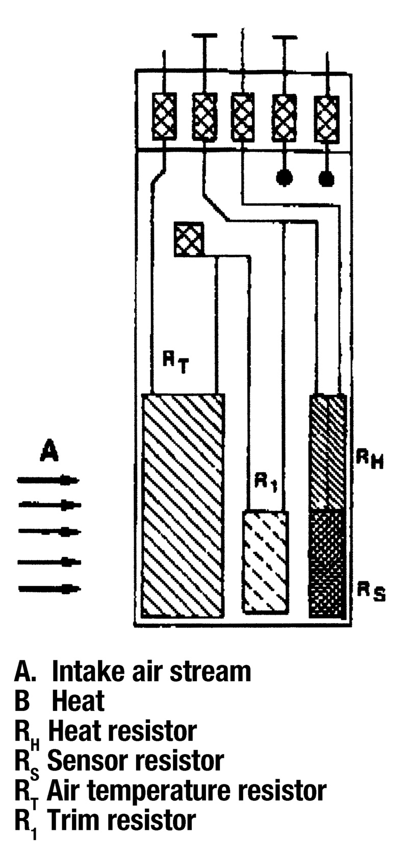
Here’s what the sensor does: The computer uses its signal to determine the minimum injected fuel quantity, the warm-up enrichment and the acceleration enrichment. It is factored into the calculation of ignition timing during warm-up and at WOT. The computer uses the MAF signal as well as other inputs to determine whether the catalytic converter is operational, when to employ the feedback mixture signal, camshaft adjustment, overheat protection, how to correct for intake air temperature and when to reduce power to protect the transmission.
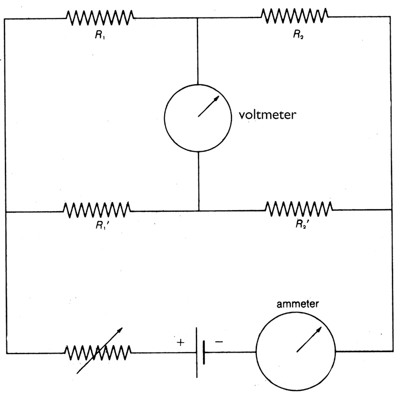 Here’s how it works to do that: Its internal resistors are arranged as a Wheatstone bridge. A Wheatstone bridge is a set of resistors of known and unknown resistance that can determine the value of the unknown resistance to great precision. The unknowns are the resistors that change value with the air temperature and (the hot-film, earlier the hot-wire) with the amount of heat carried off by the passing airstream. The electronics of the system increase or decrease the current through the Wheatstone bridge circuit to keep the voltage across the middle of the resistors at zero. While the diagram shows a rheostat, current actually varies by duty-cycle. The duty-cycle required to keep the cross-bridge voltage constant corresponds accurately (though not linearly) to the mass of the airflow.
Resistance, as we know from basic electrical theory, varies with the current flow. So for a given circuit, the resistance increases as more current passes and decreases with less current. Check the resistance through a lamp filament when it’s very bright, and you’ll find more of a voltage drop (corresponding to more resistance) than you will through the same lamp filament if you dim the light. In exactly the same way, current flow varies with the resistance, so when a larger air mass carries off more heat from the MAF element, its resistance goes down. That throws off the Wheatstone bridge voltmeter, and the electronics increase the duty-cycle and current through it, raising the resistance back to put the bridge voltmeter in balance again. Needless to say, this happens instantaneously; there is no dipping and spiking.
Things can burn out in a MAF sensor, but they rarely do. The more frequent problem is the gradual accumulation of small amounts of debris and deposits over the sensor. As these contaminants accumulate, the sensor reports an air mass that is gradually smaller and smaller than the true intake air mass. The computer can employ various algorithms to correct for this, using information from the manifold pressure and air temperature sensors, the throttle position sensor and others, finally correcting the delivered injector pulsewidth with feedback from the oxygen sensor. But this can’t go on indefinitely before the sensor signal falls outside of correction range. And while people try it, cleaning a MAF sensor frequently damages the sensor more than the original problem (if there was one).
The problem is that a false MAF signal can remain within a plausible range given throttle position and other factors, yet still be off enough to drive the mixture out of stoichiometry. At a certain point, then, SWAG-testing with another MAF sensor becomes the reasonable next diagnostic step.
WIS
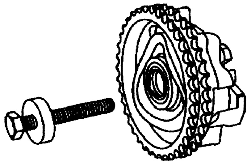 Centrifugal Advance Drum
All Diesels
If you’re changing an injection pump or even replacing a timing chain, you may have occasion to remove the centrifugal advance device at the chain-end of the pump shaft. Before you go back to the compressor to ratchet the air pressure control switch up, keep in mind the bolt holding that drum to the shaft tightens counterclockwise; it’s a ‘left-handed’ bolt. With enough force, you can turn it the other way, but not far and not inexpensively.
G/11/02
‘Stretched’ Timing Chain
Model 124 with Engines 602 or 606, Model 140 with 603
Diesel engines are very durable, but they do decline in specific ways over time. Here are the symptoms you might expect from a ‘stretched’ (i.e., worn) timing chain:
- Rattling or other noises from the chain cover area
- Rough running engine
- Hard starting
- Loss of power (consistent)
- Increased lubricating oil consumption
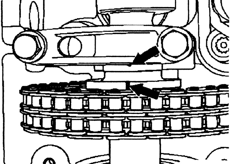 Here’s the best way to determine whether there has been timing chain ‘stretch’ beyond specifications:
With the timing cover off, turn the engine by hand with the crankshaft bolt in the normal direction until the timing mark on the camshaft lines up with the mark on the camshaft bearing cap. Then check the position of the crankshaft pulley compared to the graduated scale and the needle on the block. If the camshaft timing is off by 3 to 10 degrees, replace the timing chain. While you’re inside the cover, turn the crankshaft through two complete cycles so you can inspect every tooth on every sprocket. Some wear on the chain guides is normal, but there should not be any on the sprocket teeth.
SI 05/91
The Other EGR
 All Recent Diesel Models
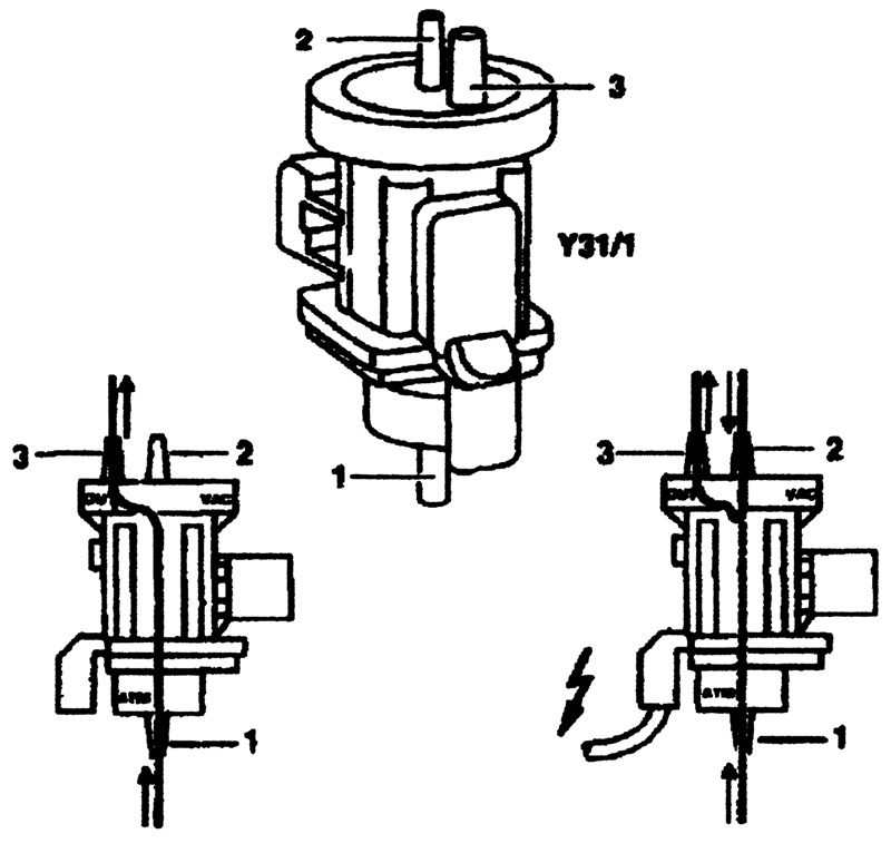
Codes flagging emissions system failures as well as driveability symptoms that point to EGR as a problem can involve more than just the EGR valve itself. Besides the EGR position sensor atop the EGR valve, one of the more likely problem areas is the EGR system’s vacuum transducer. This component connects vacuum from the vacuum pump (the same one that builds vacuum for the power brake pneumatic circuit) to actuate the EGR valve under circumstances when there should be circulation. The transducer has a pneumatic line to the pump, to the EGR valve and a vent to atmospheric pressure. It gets a duty-cycle pulsed signal from the computer to open, close or move the valve; and it achieves these objectives by connecting the vacuum source (line 2 on our diagram) to the EGR valve itself or to atmospheric pressure.
If there is no signal to the transducer, it leaves the valve closed. If its internal diaphragm fails, it leaves the valve closed. If it shorts its internal coil, it leaves the valve closed. If a leak develops between the vacuum pump terminal and the EGR, however, it can cause constant application of EGR. The system does not distinguish a failure of the transducer from a failure of the valve; you have to determine that by testing.
WIS


0 Comments