
ESP and other traction controls are not just for black ice and winter driving. Wet leaves can be as slippery as oil on the road, and even ordinary rainwater can reduce traction on smooth pavement dramatically.
In the last issue of StarTuned, we described how the Mercedes-Benz ESP system works and how its various sensors provide information for the electrical and hydraulic control units. This issue, let’s shift to the components that do the traction control work, how to isolate and solve any problems that come up and conduct a few thought-experiments that can be useful both for diagnosis and for understanding.
What say, we work conceptually backwards from the actuators to the controls? The final actuators, of course, are the four tiretread patches against the pavement. As with the earlier traction-controls and any yet-to-be-developed analog systems, ESP cannot recover from slipping and skidding forces that exceed the maximum traction available at the individual wheels – from maneuvers, in other words, that would violate established laws of applied physics.
If you hold a car at 75 mph and suddenly crank the steering wheel to full lock, you’re going to lose control of the vehicle with almost any set of tires, on almost any pavement. With ESP and Mercedes-Benz’ carefully engineered steering and suspension, you’ll retain control for a fraction of a second longer, but you’ll still lose it, no matter how powerful and complex the car’s traction control system. As we said last issue, it’s machinery, not magic. Neither ESP nor any other traction control system can achieve maneuvers requiring more traction than the tires and pavement can deliver.
ESP incorporates the earlier traction control systems ASR and ABS as subsystems of itself, as we mentioned last issue. Though we’re focused here on the ESP side of the system, they’re only separate because we talk about them separately. It is interesting to notice certain symmetries and asymmetries among them. ABS, the oldest system, can work on all the brakes, but can only reduce or release brake hydraulic pressure. ASR can actively apply – increase — brake pressure, but only to one or the other or both of the two drivewheels, not to the freely rolling fronts (we’ll get to the system complications with 4MATIC and 4ETS next issue). ESP, the latest traction control, can only activate one brake at a time, whichever its electronic algorithms designate as the wheel that can correct sideslip on the other axle, in response to all the sensor inputs. Of course, it’s the same electronic and hydraulic control units performing each of the traction control functions, so the distinction between the subsystems is logical, not mechanical, hydraulic or electrical.
The ESP system is not just the sideslip control sensors and measures. Subsumed into ESP are our old friends ABS and ASR, as subsystems within the overall traction control. There are malfunction indicator lights on the dash that reflect the state of the system. It is possible to lose one function without losing all of the others, depending on circumstances. If something disables the electronic accelerator system, for instance, ASR cannot employ all the tricks in its engine output torque repertoire. But the overall system can still activate each of the ABS and ESP brake functions, which are generally independent of the engine. Certain failures, however, like a low charging system voltage or an open-circuited wheelspeed sensor, may affect or disable all of the traction-related subsystems.

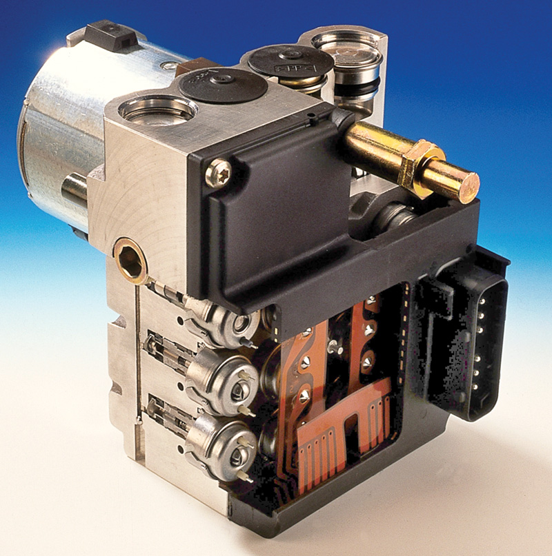
Circuits, hydraulic and electrical, are the muscles and nerves of the ESP traction controls. The hydraulic control unit straddles the brake lines between the master cylinder and the four calipers. It includes the pressure pump and the solenoid valves for all ABS, ASR and ESP actuations. The control unit resides in the electrical control unit compartment, just in front of the bulkhead in most car models.
Self-Diagnostics
The ESP system does much of the diagnosis for you. When you first turn on the ignition key, the system goes through the ordinary bulb check, not just for the traction control systems, but for everything that appears on the instrument panel. When the engine starts, it runs a basic self-test. Among the other items checked are voltage supply, continuity through sensor and actuator circuits and plausible position information from the various switches.
Two dynamic self-tests follow, one as the vehicle just exceeds 6 km/h (about 4 mph) and the second at 15 km/h (roughly 10 mph) as long as the engine speed simultaneously exceeds 2500 rpm. If the system tests functional, the indicator light stays out, and the ESP traction control is at work. The triangular warning lamp, with the exclamation point symbol, does not indicate any problem with the system. Instead, that warning lamp flags driving conditions in which the system is actively taking steps to maintain traction. A driver should reduce his speed and moderate his driving style when that lamp flashes, because he has approached the limits of traction adhesion.

For testing both harnesses and individual components, understand how the connectors lock before you release them. None of them should require force beyond the stiction of the terminals themselves, but most do have a locking tab or other mechanism to keep the connection secure.
When traction is sufficient for the moment, the ESP hydraulic control unit rests with all its solenoids and valves in their deactivated position, passing whatever hydraulic pressure the driver produces in the master cylinder along to the wheel cylinders when braking. Only when there is wheel slip, from excessive braking, excessive engine torque for conditions or axle sideslip do the pumps and selective valves get to work to control the direction of the vehicle according to what the driver evidently wants, as indicated by what he does with the pedals and steering wheel.
You can test each solenoid’s coil individually through the connector. They should be approximately the same, since it is quite unlikely they have all failed simultaneously in exactly the same degree.
Active Diagnosis
When doing a complete diagnostic sequence, it is helpful to have the full scope of Mercedes-Benz diagnostic special tools to analyze problems that come up with the ESP system. But for a quick pinpoint diagnosis, most of the sensors and actuators work in ways you can test directly with an ordinary volt-ohmmeter. For some tasks, an oscilloscope can provide additional information. For mechanical and hydraulic work, you can work on individual wheel calipers, replace hoses, flush fluid and all the routine brake work in familiar ways.

The electric pump in the hydraulic control unit provides both the activation pressure and returns the brake fluid to the master cylinder once the traction-control event is complete.
Many of the sensors and inputs are just on-off switches, even though their effect on the system may be more complex. The ESP-off switch on the dash, for instance, is an ordinary continuity switch, but when turned off it tells the system to restrict ASR operations to brake actuations only. The test for the switch is, thus, simple. The test for the system is dynamic – drive the car and see whether it does what it is supposed to. Other inputs, however, require more detailed diagnostic approaches. Let’s look through them.

Release the tab lock to disconnect the electronic control unit harness for testing the continuity of circuits and such diagnostic procedures. As with all complex systems, the temptation is to suspect the most complex element of the system when there is a problem, while the probability is that any problem results from something much simpler and – if you do a careful visual inspection – more obvious.
The muscle for ESP’s brake activation comes from the electric quill pump in the hydraulic control unit. Because the ESP pump is of higher capacity than earlier electric hydraulic pumps, there is no need for a pressure reservoir to store active pressure for brake applications, though most models include a hydraulic accumulator to reduce noise and brake pedal pulse as well as individual acoustic silencers on each brake circuit. ESP functions ordinarily require less hydraulic pressure and volume than ASR since they only apply to one wheel at a time and since it requires much less brake force to prevent excessive yaw than to rein in the engine torque. Since the fluid in a hydraulic system is incompressible, the pressure application at the caliper is practically instantaneous when the control unit activates the solenoid valve.

The pressure transfer piston unit separates the hydraulic control unit from the master cylinder. Its chief purpose is to retain pressure in the ESP-activated wheel circuit, not returning it to the master cylinder until the event is over.
The quill-type charging pump builds 7- to 15-bar pressure. Its pressure is internally regulated in the hydraulic control unit. If you actively test the system, don’t run the pump longer than one minute. Most vehicles run the pump briefly upon engine startup as part of the system’s initial self-testing procedures, and that can let you know what the pump sounds like (it’s audible even with engine running and the hood closed). If you don’t hear the pump, start chasing powers and grounds.
ESP Pressure Transfer Piston
, i silicone oil, k spring metal diaphragm")
Included at the left end of the pressure transfer piston unit is the hydraulic pressure sensor. Elements: a electronics, b brake fluid under pressure, c wire, d case, e glass element, f insulator, g reference pressure, h pressure sensor (strain gauge), i silicone oil, k spring metal diaphragm
This component connects the hydraulics between the master cylinder and the ESP hydraulic unit. It functions to separate the brake pressure built up by the charging pump for ESP application from the rest pressure in the master cylinder. This component also has the brake pressure sensor incorporated at one end. The pressure transfer piston actually contains two separate pistons, held in their normal position by springs in the cylinder bore. In their normal position, the brake circuits are both open for ordinary braking purposes. This unit is ordinarily just behind the left front wheel on the fender.
The signal from the brake hydraulic pressure sensor is one of the inputs to the electronic control unit in calculating whether and how much brake force toapply to a given wheel. Interesting aspects of this feature are its range and threshold. It can report up to 200 bar, though even 100 bar (1500 psi) would be a very forceful brake application. The system regards a tolerance of +/- 17.5 bar as accurate. This suggests to us the conjecture that ESP does not require finely detailed information about hydraulic pressure, perhaps largely signals that pressure has increased or decreased.
The sensor requires a 5-volt reference feed and ground, and it has a signal return. While we don’t have any suggestions to check its accuracy (what would be your more accurate gauge to measure brake hydraulic pressure?), you can check its output to see whether there is any change when you press and release the brake pedal. Like most electronic devices, it may short or open, but it is unlikely to get out of adjustment.
, or you can measure it directly. Gently unbolt the sensor and lay it on one side, observing the output signal. Then lay the sensor on the other side, watching for the change of signal. Remember the sensor is delicate, so don’t drop or strike it.")
The lateral acceleration sensor is a Hall-effect device at the center of the car, as described last issue. The HHT can access this sensor (you grab the roof rail and rock the car back and forth to see the signal respond), or you can measure it directly. Gently unbolt the sensor and lay it on one side, observing the output signal. Then lay the sensor on the other side, watching for the change of signal. Remember the sensor is delicate, so don’t drop or strike it.
Stop Lamp Switch
ESP uses the same multiple-circuit stop lamp switch used on most cars without ESP: one contact is normally open; the other normally closed. Both must make and break connection in the expected way for the system to determine the brake pedal is in use. Check for power to the switch as well. The larger pins are for the normally open circuit, and the smaller pins for the normally closed.
Master Cylinder Switchover Valve
Inside the master cylinder is a device to take advantage of the ABS system: the switchover valve. While it is not unique to cars with ESP, it allows equal hydraulic pressure to front and rear wheels (thus a 60/40 front/rear braking force, given the relative size of the pistons), achieving more uniform brake pad and tire wear. In the absence of ABS, this could represent an increased chance of rear wheel lockup, but the ABS system protects against that as long as it is functional. If it turns off for some reason, that de-energizes the switchover valve, making the hydraulic pressure 70/30 front/rear, further hydro-mechanical insurance against rear brake lockup.

The yaw sensor, as we saw last issue, measures the rotation of the vehicle around its vertical axis and sends that information, encoded as a voltage, to the electronic control unit. While HHT testing is easier, you can test this with a voltmeter. In a clear space with no risk of striking any obstruction, turn the steering to full lock and drive at about 4 mph. This should complete a 360 turn in about 18 seconds. If you turn to the right, you should see close to 1.78 volts; if you turn left, you should see about 3.22. The sensor receives a 5-volt reference signal and produces a 2.5-volt comparison signal at pin 4. The purpose of this signal is merely to give the control unit something to factor against electrical noise in the circuit (the noise will affect the 2.5-volt signal in the same way and to the same extent as the ‘real’ signal.
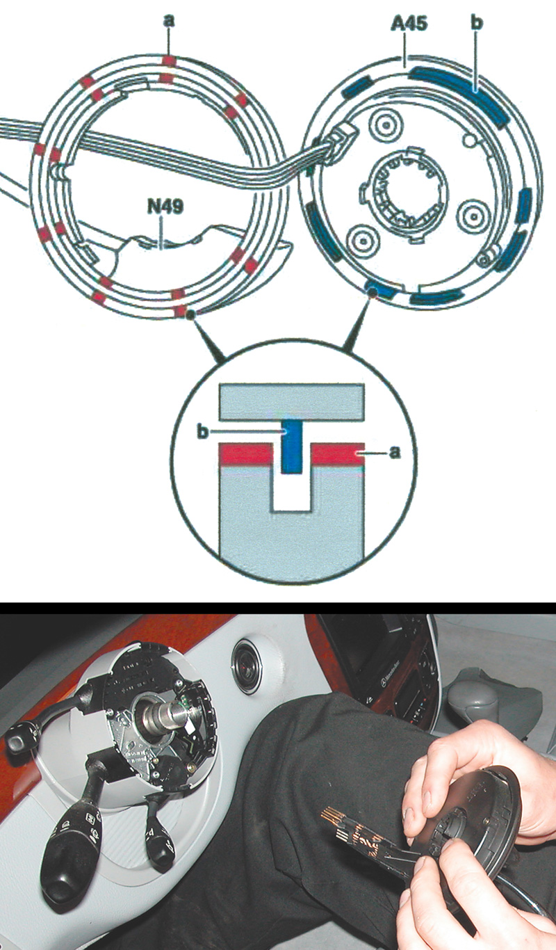
The steering angle sensor works by precisely segmented blades interrupting the optical signal between individual sensors, as described last issue. The output signal from the sensor is a digital stream generated by its internal microelectronics from the raw data from the light receptors. While in principle you could decode the digital stream, this is another case where the best procedure is to merely check for its appearance. An oscilloscope is best for this test. A new sensor or one that has lost its power and ground connections will have to be ‘re-initialized’ as described last issue.
Wheelspeed Sensors
Finally, and the most common reason for ESP problems, the wheelspeed sensors are the same inductive pickups familiar from ABS and ASR. Riding where they do, exposed to road hazards, with their connector harnesses flexing back and forth with every suspension movement, wheelspeed sensors can become nonfunctional, especially on high mileage cars, merely because the circuit goes intermittently open.
The best way to check them is with an oscilloscope. ESP cars have wheelspeed rotors with 48 teeth per revolution, and the standard the control unit looks for is a minimum of 0.12 volt AC. With the oscilloscope connected to the two wires from the sensor, spin a wheel and watch the pattern. A notch in the pattern every 48 cycles suggests a damaged tooth or a piece of ferrous metal caught between two teeth. A constant misshapen pattern suggests a cracked magnetic pickup, or a piece of ferrous debris sticking to the tip. No signal at all suggests a broken wire.
The sensor also conducts its internal self-test when the control unit sends it a 20 ms 5- volt signal to pin 5. If it passes this test, it responds with a 3.40 (+/- 0.32 volts) signal momentarily at the output pin.
Thought ExperimentsTesting and experimentation are critical research in the design and manufacture of vehicles, as Mercedes-Benz has done for over 100 years. Some experiments and testing require precision instrumentation and measurement, but other types – the thought-experiments we’ll consider here – are entirely instruments of the mind. Mercedes-Benz tests the cars they make. These tests range from the very dramatic, like crash tests, to the mundane, like wheelspeed and temperature tests. All these tests contribute to improving the quality and performance of cars over time. Thought-Experiment One Fixed CircleImagine a wide, flat section of good pavement. There is a circle painted with a 100-foot radius and another concentric circle with a 110-foot radius. The object is to drive the car in the space between the painted lines, gradually increasing the speed until centrifugal force overcomes traction and you can’t control the car within the 110-foot circle. Without ESP, the car can maintain the circular path (with increased body lean and tire squealing) up to the point at which the axle with lower traction can no longer hold its end of the car in the chosen path. If that’s the front axle, the car will understeer and nose out of the circle, regardless of steering angle input. If the rear axle comes loose first, the car will oversteer and pivot toward the center of the circle, sliding sideways to a halt. Oversteering cars can slide toward the circle center or outward, depending on a variety of chassis and steering dynamics not directly relevant to our thought-experiment. With ESP, what happens? If the car understeers because the front axle is sliding outboard, the system applies the inside rear brake, pivoting the car back onto the intended track. Does this mean the circular speed can be increased indefinitely? No. Our conceptual car’s drive axle has one wheel pushing the car forward and the other pulling the car back, with just enough difference in force to keep the front axle from sliding out of the track. But working against itself like this, either the force on the drivewheels will become equal and the speed will stay constant. Or the car will increase up to the combination of centrifugal and traction forces such that it slides outside the circle with all four wheels sliding roughly the same. This will, of course, be a somewhat higher speed than the non-ESP car could manage. But the ESP car cannot accelerate indefinitely, either. (If we added ASR to our thought-experiment, the car would reach the speed at which the second drivewheel started to slip. And then the system would apply drivewheel brakes and/or reduce engine torque output. The car would reach and hold its maximum traction speed, but would not slide out nor increase in speed. Limiting factors would be rapid wear of the outside tires and the driver’s rapidly eroding sense of balance.) If the car oversteers, with the rear axle sliding outward, the system applies the outside front brake to correct the excessive yaw. It would be interesting to know whether the outside front brake might have more effect than the inside rear on the understeering car, supposing that the additional traction of the weight shift would have such a result. But now we have the rear drivewheels pushing forward and the outside front braking. Just as with the previous example, this can’t continue beyond a certain speed, at which the car slides outside the circle, with all four wheels ideally sliding equally. What’s the point of this thought-experiment? No matter what the dynamic conditions of a constant turn, there is a speed beyond which the car cannot go, ESP or not. A motorist who reports his ESP system does not maintain traction control could possibly be trying this thought-experiment on real-world roads. Thought-Experiment Two Straight Line Into CircleHang onto that painted conceptual circle. Now let’s approach it in a straight line that enters the circle where they intersect. Hold a constant speed along the straightaway and into the circle. Clearly, below a certain speed, there is no problem at all. The car just makes the turn and continues around the circle in control. Above that speed, we encounter a situation almost exactly the same as our first thought-experiment. There will be a speed above which the car will understeer or oversteer out of control, ESP or not. In fact, this may be an easier slide to achieve than our first example since ESP will do nothing to restrict the approach speed to a pace that can maintain the circle. Aside from that, the major difference is that the car abruptly yaws as it begins the circle. This compels the ESP system to actively balance traction just as the curve ensues, at least at the limits of traction. As with the constant circle, the car with ESP can take this path somewhat faster than a car without, but it can’t do so without limits. Thought-Experiment Three Progressively Banked RoadFinally, let’s consider a dead-straight road, but one that gradually, over the space of a mile or so, tilts more and more to the side, all the way to 90 degrees. No car, ESP or not, will make it all the way to the place where the road surface is perpendicular to the surface of the earth. But how will an ESP-equipped car work differently from one without? Can it travel any farther down the ever-tilting road, and if so, how? We can dispose of the non-ESP car simply enough. One or the other axle starts to slide to the side, and the car moves off the tilted road, either front axle first (understeer) or rear axle first (oversteer). It does seem odd to speak of a car either understeering or oversteering with the steering wheel held dead center, but that’s exactly what’s happening. The ESP car will also slide off the road, but what can the system do to forestall the slide? Can it hold onto the pavement longer? As the car tilts, neither the yaw sensor nor the steering angle sensor reports much change to the control unit. True, the driver will have to turn slightly uphill to counteract the drift from the road bank. The car’s vertical axis rotates with the road surface, but the car does not rotate around the axis, so the yaw sensor reports nothing amiss. The lateral acceleration sensor, however, maps the road tilt exactly, so the control unit certainly can calculate increased side-load and the imminence of a sideslip. At the very moment one or the other axle starts to slide off the road, the yaw sensor detects vehicle rotation around its vertical axis, even though the vertical axis is now tilted substantially to the side. From the direction of rotation, the control unit can determine which axle has begun to slide. From the lateral acceleration sensor, the control unit can tell there has been a sudden reduction in lateral acceleration, because the car is now moving to the downhill side. That movement reduces the traction the tires would otherwise transmit.
|


0 Comments