One of the last remaining sources of air pollution produced by vehicles occurs during refueling. As fuel is pumped into the tank, fuel vapors are displaced. Unless these vapors are trapped, they will escape into the atmosphere via the fuel filler neck.
Many jurisdictions now require the use of special gas pump filler nozzles, which capture the vapors as they escape. Many late model vehicles also incorporate an onboard refueling vapor recovery system, which captures the vapors before they have a chance to reach the filler neck. Subaru first added this capability to its vehicles during the 2000 model year.
Operation of the evaporative emissions and fuel recovery systems is monitored by the onboard diagnostic system (OBD II). The system periodically checks the system for leaks, to prevent vapors from escaping into the atmosphere.
The system has the ability to detect a leak caused by a hole that is not much larger than a human hair in diameter.
If a leak is detected, the OBD II system will set a diagnostic trouble code (DTC). This is where you enter the picture. The source of the leak must be identified and repaired. If not, the DTC will reset the next time the OBD II system runs its diagnostic checks. Testing the onboard refueling vapor recovery system involves checking all solenoids, valves and plumbing for air tightness, air flow and proper operation. A failure in any of these items will create a failure in the system.
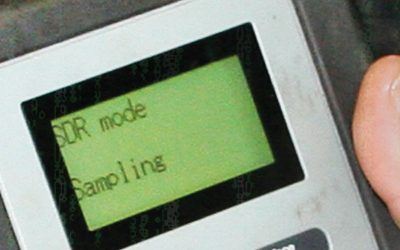
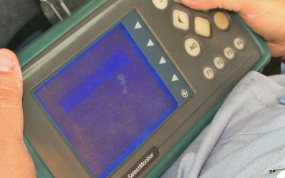
The evaporative system pressure tester must be used with the Select Monitor (or a compatible aftermarket scan tool) to achieve the correct results. Begin by reading the warnings included with the special tool. Section by section testing will ensure all fittings, hoses, pipes, valves and components are tested.
Evaporative Emission System Tester Component Legend
| PT | Pressure Tester | F | Fuel |
| CPC | Canister Purge Control | FH | Fuel Hose |
| M | Manifold | PCV | Pressure Control Valve |
| D | Drain | V | Vent |
| SOV | Shut Off Valve | PS | Pressure Sensor |
Pressurizing the Tester
The following steps must be followed to pressurize the tester when instructed to do so:
- Place the Pressure Hold in the open position.
- Place the Vent in the closed position.
- Turn the pump timer ON.
- Observe the gauge.
- When the highest pressure is reached, place the Pressure Hold in the closed position.
- Turn the pump timer off.
Abbreviation | Component | Location |
| CPC | Canister Purge Control Solenoid | Right under side of intake manifold. |
| PCV | Pressure control valve | Above rear differential. |
| D | Drain valve | Above canister right rear of vehicle. |
| SOV | Shut Off Valve | Located on the fuel filler neck behind the right rear inner fender. |
Troubleshooting the evaporative emissions system involves a sequence of tests, listed below:
- Purge System Test
- Drain System Test
- Shut Off Valve Test
- Pressure Control Valve Test
- Fuel Tank and Vent Control Valve Test
- Canister
Follow the directions in each of the above tests. Complete all six tests to evaluate the entire evaporative system. Directions are included in each test to guide you through results that indicate a failure. Always complete the six tests, even if a failure has been identified and repaired early in the test sequence.
Purge System Test
- Disconnect CPC-1 from M-1.
- Start the engine and check for a strong vacuum source at M-1.
- Turn the engine off and ignition off.
- Connect the Select Monitor to the data link connector.
- Connect the inspection mode connectors.
- Turn the ignition on and engine off.
- Turn the Select Monitor on and adjust to the system operation check mode. Activate a component and turn it off to establish full control of all system operation check mode items.
Step 8 and 9 test the air tightness of the vacuum line from the intake manifold to the canister purge control solenoid. The air tightness of the solenoid is also checked at this time.
8. Connect PT-1 to CPC-1 and pressurize.
9. Did pressure hold?
If YES, go to step 10. If NO, go to step 10F.
Step 10 and 11 test the electrical and mechanical operation of the canister purge control solenoid and the vacuum line from the output side of the solenoid to the canister for restrictions or blockages.
10. Disconnect CPC-16 from the canister.
11. Activate the CPC solenoid with the Select Monitor.
12. Did pressure immediately go to zero?
If YES, go to step 13. If NO, go to step 13F.


0 Comments