New technologies under the hood call for new tools and equipment to locate and fix those pesky starting and charging problems.
Very little is more frustrating than troubleshooting elusive starting and charging problems. To make matters worse, vehicle electrical systems vary, not only from brand to brand, but by model and year within a brand. Many times, the problem can be permanently solved by using basic testing procedures in a systematic way. But, things have rapidly changed in the electrics under the hood and Subaru vehicles are no exception. In order to test, diagnose, repair and service these newer systems, your information and equipment will have to be up to the task.
First and foremost, you must have the correct specifications and information at hand for the particular model you are servicing to accurately diagnose and repair electrical problems. Subaru makes repair information available through your local Subaru N.E.W. Horizon Dealer, or on the Subaru Technical Information System website at http://techinfo.subaru.com. Also, two helpful Technician’s Reference Booklets are available: Basic Electrical Theory & Diagnosis, Module 601, item MSA5P0134C and Advanced Electrical Theory & Diagnosis Module 602, item MSA5P0134C.
The Right Stuff
Before we delve into the procedures for diagnosing battery, starting and charging problems, we should address the necessary tools. You’ll need to have the right equipment to test the latest computer-controlled electrical systems. Make sure your charger and diagnostic tools are up-to-date and compatible with newer systems. A basic arsenal of test equipment should include:
- Digital multi-meter (DMM, formerly known as a digital volt-ohm meter, or DVOM)
- Electrical System Analyzer
- Battery Charger
- Scan Tool
If you are fortunate enough to have a dedicated lab scope in your shop, that’s even better.
Digital Multi-Meter
Long gone are the days when checking a battery or electrical charging system could be performed with a simple voltmeter and test light. The sophisticated electronically-controlled systems on late model vehicles require the diagnostic capabilities of a digital multi-meter. The most acceptable method for checking battery draw is with the use of
an ammeter with an inductive pickup. DMMs usually have a DC ammeter function that will read from a few milliamps (mA) up to 10 amps. Make sure your DMM is internally fused for protection against high amperage. With the use of an induction clamp, or “amp clamp,” you can observe the ampere variance as accessory loads are applied.
Electrical System Analyzer
Many new electrical system diagnostic tools are on the market today. These dedicated analyzers read the conditions existing in the electrical system and signal malfunctions or weaknesses. They also direct corrective measures and verify that the problem was eliminated by the repair.
Many of these tools not only test the condition of the battery, but also monitor alternator output, check diode condition, and find short circuits. Rate of discharge is measured by internal microprocessors and compared against known standards to establish “rate of decay” and recovery ability to predict the power-holding potential and life expectancy of the battery. Another approach is to measure the conductance quality of the battery by sending a frequency signal through it to estimate the usable plate area, thereby determining the power retention life. Cold cranking capacity (CCA) is also measured, both without and under load.
The end result is more accurate decisions on borderline batteries, and the identification of battery defects even at extremely low voltages, thus eliminating the time-consuming need to charge and retest the battery.
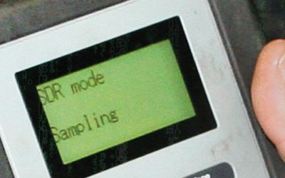
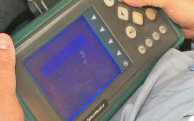
A good example of the latest technologies for analyzing and testing the starting and charging systems is the inTELLECT EXP -1000, made by Midtronics. This handheld analyzer allows a technician to diagnose every part of the electrical system, from the battery to the starter and alternator. Test results can be printed out via an optional printer. The tool’s expandable platform combines the full functions of an advanced analyzer, digital multimeter (with scope mode), and data management tool. It’s upgradeable for future applications and features.
Modern Chargers
The newest types of battery chargers have also been integrated with computerized logic and databases to determine the quality of the battery, its life expectancy and to provide optimum charging. Many can measure over 1,000 amps of starter draw using inductive amp probes, and voltage drop at connections and cables with test leads. These units can also test alternator output with carbon pile load, and detect bad diodes and faulty stators with an automatic ripple indicator. Some units even have battery decay logic programs to determine battery life expectancy.
The Midtronics GR-1 features “diagnostic conductance controlled charging” for solving battery problems. It tests the battery at the beginning, during and after charging. This unit effectively controls the charging process using the optimal charging voltage and current to quickly charge even weak batteries.
Scan Tool
While a scan tool isn’t the first tool you may think to grab when troubleshooting a starting and charging problem, it can give you insight into any malfunctions in other areas of the vehicle that could have a bearing on the electrical problem. Be sure to check the ECM for any diagnostic trouble codes (DTCs) prior to tackling the problem. It can save you a great deal of time and effort.
Battery Testing
Begin your troubleshooting efforts with the battery. You’ll need to determine the state of charge, the battery’s condition and its ability to hold a charge. If the battery is in good condition, it will hold a charge and deliver its rated amperage as needed. If the battery is in poor condition, it won’t deliver on demand.
Use a voltmeter or DMM to check the charge level. Don’t trust the battery’s integrated charge indicator as it may only be reading one cell, not all. When fully charged, a battery should read 12.6 volts at room temperature. At 75% charged, the reading will be 12.4 volts. Lower readings indicate the need for recharging. Test the battery with an analyzer to determine its condition and ability to hold a charge. If you don’t have an analyzer, recharge the battery, then retest it.
The following steps can be taken to check the battery:
- Check the battery for physical damage.
- Check the positive and negative leads for corrosion and proper installation.
- Check that the electrolyte is at the full level.
- Check the color of the electrolyte to assess plate deterioration:
- Clear means there’s no damage or deterioration.
- Red means there’s positive plate deterioration.
- Gray means there’s negative plate deterioration.
- Check the specific gravity. It should be at least 1.230 at room temperature to test the battery. There should be no more than a .050 point differential among the cells.
- On sealed maintenance-free batteries, check the open circuit voltage and compare its value with the manufacturer’s specifications. If the specific gravity is below 1.230 or the open circuit voltage is below the recommended value, charge the battery and recheck the specific gravity or open circuit voltage.
Adding Juice
Before recharging (or replacing) a battery, check the operating condition of the charging system. Refer to the vehicle’s service manual for correct specifications. As a rule, it should read 14 volts during idle, with all accessories off, but may vary according the battery’s condition, charge level, load, ambient temperature and design. Cold weather will normally raise the charging level, while hot weather will normally lower it. If you have a tester with an adjustable carbon pile, you can check the charging output while the engine is operating at 2,000 rpm.
Alternator
Before testing the alternator (or installing a new one), make sure the battery is fully charged and in good condition. Remember that the alternator’s job is to maintain the battery’s charge, not to recharge a faulty one. Use a DMM or system analyzer to test the alternator output. Make sure the belt is in good condition and the tension is correct. Most electrical system analyzers and testers can also detect a faulty diode.
Starter
Just because a starter spins when power is applied is not an indicator that it is free from problems. In order to get an accurate reading, you’ll need to check how many amps it is drawing and measure the spin speed. It may be necessary to use a bench tester if your equipment in not capable of measuring the starter’s rotating rpm. Check the OE specs for the starter and compare to the unit you’re testing.
Starter malfunctions can be caused by a faulty solenoid, shorts or opens in the field coil or armature, worn brushes, shaft damage or corrosion – internally or on the connections.
Subaru recommends a starter performance test under these conditions:
- No-load test (free spin).
- Load test (under applied load).
- Stall test (armature locked).
While specifications will vary, we’ll use a 2000 Legacy with an automatic transmission as a typical example. Measured values must meet the following standards:
- No-load test @ 11V/90 A, or more, and the rotating speed must be 3,350 rpm, or more.
- Load test @ 8V/13.7 Nm (10.1 ft-lb), 370 A or less, and the speed must be 880 rpms, or more.
- Stall test @ 5V/1,050 A, or less, and the torque must be 27.5 Nm (20.3 ft-lb), or more.
Of course, remember to consult the Subaru Service Manual for the vehicle you are diagnosing for the correct specifications.
How’s the Weather?
The local temperature and weather play a big part in starting and charging problems. People who live in the northern part of the country know that cold temps wreak havoc on batteries, alternators and starters — and expose any weaknesses in the system.
When the mercury dips, the battery’s power is reduced by significant numbers. A fully-charged, battery is essential to spin the starter at speeds necessary to turn over the engine. Meanwhile, the engine oil has thickened and engine metal has contracted, making the job of moving the pistons, valves and the viscous oil much harder on the starter. More cranking amps are required to handle the load. At the same time, the driver may have turned on his heater/defroster, windshield wipers, rear window defogger, seat heaters and radio. The demand on the charging system has just maxed out!
Not only does the power demand tax the system, but in many cases the electrical accessories may be the cause of electrical problems. When searching for elusive electrical gremlins, first check the starting and charging system with all accessories off. If the problem is not found, one by one, turn each electrical accessory on, until the problem is isolated.
Those of you who live in areas that use salt to de-ice roads need to check for salt corrosion on exposed terminals, grounds and connections.
Hot climates can cause electrical system problems, too. For one thing, batteries don’t like excessive heat. Electrolyte evaporation and high temps promote battery deterioration. Also, the radiator and A/C cooling fans, blowers and the compressor clutch all add to the electrical demand.
In short, extreme temperatures place high demands on the battery, starter and charger, so always take the climate into consideration during diagnosis.
We’ll conclude with one crucially important, yet often overlooked, point that applies to all electrical troubleshooting: Always check for good grounds before you condemn any components.
Download PDF


0 Comments