With the advent of dual and multiple zone HVAC, we now have multiple heater cores. So if the water pump is busy pumping coolant through the engine and radiator, what’s providing coolant to the heater cores?
One important part of an HVAC (Heating, Ventilation and Air Conditioning) system is, of course, heating. Passengers naturally like to be able to control the temperature inside the cabin, and during those cold winter days, or even chilly summer nights, keeping warm and driving with a clear windshield has a lot of engineering behind it.
Always keep in mind, though, that a cooling system’s main job is to keep the engine from overheating. Heating the inside of the vehicle is just a by-product of this process. But vehicles are subject to a diverse array of driving conditions, perhaps flying down an “Autobahn” at breakneck speeds, or stuck in traffic for hours at a time, so the cooling system must be very flexible. With low engine revolutions and an open thermostat, it may be difficult to supply an adequate volume of hot coolant to the heater core(s). Also, take into account the plumbing that’s required and the position of the heater core, which may prove to be a challenge for even the strongest water pump. Consideration must be given to accommodating these extreme conditions.
Consider This!
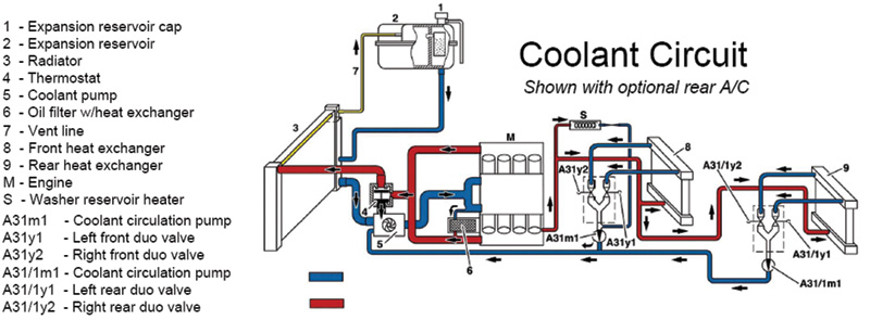
Since the early 1980s, Mercedes-Benz has used an auxiliary coolant pump to provide an adequate volume of hot liquid to the heater core. With dual- and multiple-zone climate control systems, the volume of the heating system has increased throughout the years. An auxiliary coolant pump was a well thought-out way to manage this additional volume. If you look at a typical Mercedes-Benz heater system (Figure 1), you’ll notice that the heated engine block coolant is sent directly into the heater core. In the case of this diagram, this vehicle has rear climate control. Fluid flow is directed through the heater cores, and after it leaves it is passed onto the “Duo-Valve” (A31y1, y2). Its job is to regulate how much coolant is allowed to flow through the heater cores. If the valves are wide open, flow is at maximum. If the valves are commanded closed, no coolant flow will occur. With both dual and rear climate zones, there is a large heater system volume. To deal with this volume, the next stop after the Duo-Valve is the auxiliary coolant pump (A31m1). This is designed to pull coolant out of the heater core(s) through the Duo-Valve. The more coolant it can pull out of the heater core, the more can enter the heater core. This is important to know when diagnosing “low heat” complaints — more on that later. After leaving the auxiliary coolant pump, coolant is then returned to the engine’s water pump for recirculation. And so the process continues.
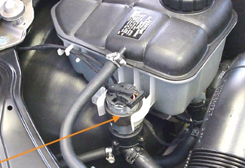
On a 2001 C280 (203 chassis, Figure 2) you will see a slightly different pump design, but the function is still the same.
Who Pulls Who’s Chain, and When, and How?
The auxiliary coolant Pump is not required in all situations. It does not alter the temperature of the heater core. It is only activated at or near maximum heat demand conditions. It does not matter what position the air flow mode doors are commanded. So, do not expect to see the pump commanded on all the time. The engine water pump can provide enough coolant flow for smaller heat demands, and during air conditioning operation the Duo-Valves are commanded closed anyway.
Mercedes-Benz also had a function called “Rest”. Pushing this button on the HVAC control panel while the engine is stopped continues to energize the auxiliary coolant pump. Residual heat from the engine coolant cycles through the heater core to maintain cabin temperature even though the engine is off. These are the only times you will see the auxiliary coolant pump operating.
On most vehicles of the 1990s, the pump is controlled by the heater control unit. This provides power to the Switch-over valve block for the mode door control, the Duo-Valve, and the auxiliary coolant pump motor (it supplies the ground to turn the pump on). Pulse-width modulation is not used. The pump is either on or off — there is no variable speed control. After the Front SAM (signal acquisition module) was introduced, it took over control of the auxiliary pump. For example, on a 2001 C280 (203 chassis, Figure 2) you will see a slightly different pump design, but the function is still the same. This pump has two wires. The Front SAM still provides the power supply, but now the pump is directly grounded to the chassis. The command to energize the pump still comes from the climate control unit through the CAN. The HVAC wiring diagram will direct you toward the Front SAM, so remember that you have to look in the SAM wiring diagram to find the auxiliary coolant pump wiring.
The Reason We’re All Here
Let’s say you get a customer with a low-heat complaint. Now you have to diagnose the problem. This condition can come from a bad water pump, a stuck-open thermostat, a blocked heater core, a stuck Duo-Valve, or a seized auxiliary coolant pump motor. How are you going to decide which part to replace? Without getting in too deep, when diagnosing a stuck-open thermostat it makes sense to let the engine get fully warmed up at idle and monitor coolant temperature, either directly or through the coolant temperature sensor on a scan tool. Then, take the vehicle on a road test and at a steady state cruise see how much the coolant temperature drops. If it drops excessively the thermostat may be stuck open. If the coolant temperature increases, the water pump may be weak.
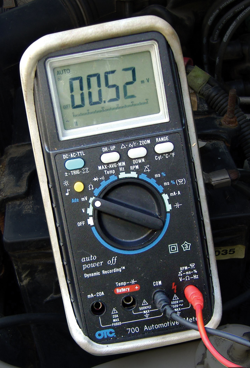
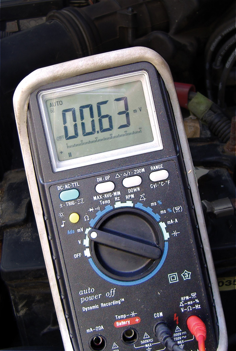
On the ’96 Mercedes-Benz E320 shown, the current draw was .5 amp at cold start-up (on this DMM with its current clamp, 1 mv equals 1 amp).
Check for a blocked heater core by removing the two hoses from the core to the Duo-Valve. With these lines off and routed into a container, you should see a strong flow of coolant with the engine running. If the Duo-Valve is stuck, very often you will get the complaint of insufficient heat on one side of the cabin. By electrically unplugging the Duo-Valve, it should default to full heat on both sides. Now, how do we check the auxiliary coolant pump motor?
What To Do?
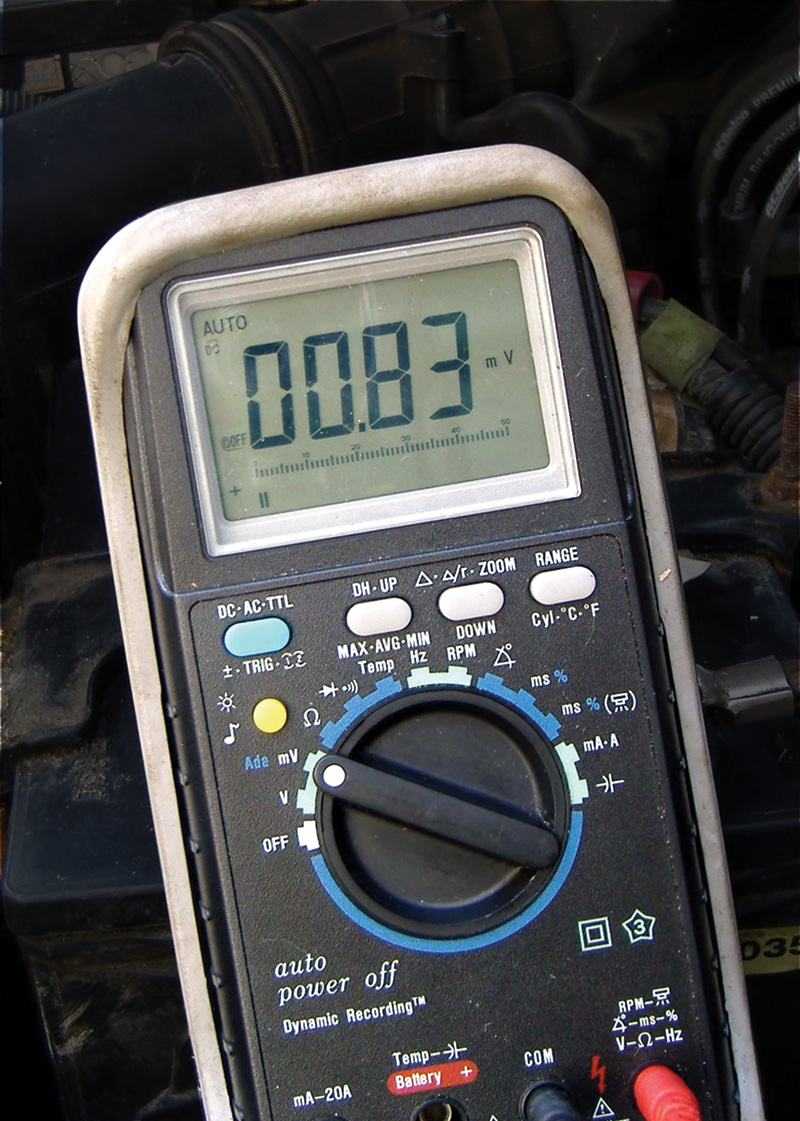
With its current clamp, 1 mv equals 1 amp). As the engine warmed up, the amp draw increased to as high as 1 amp, but eventually settled down to .8 amp .
The first step in our test procedure is to determine if the auxiliary coolant pump is being activated. To command the pump on, the temperature should be set to maximum heat and the blower motor set to high speed. If you see a “Rest” button on the climate control panel, you can push that also. Often, you will find a red wire with a tracer and a brown wire with a tracer connected to the pump. The red wire is the voltage supply and the brown wire is the ground command. There should be 12 volts between the power supply and ground with the pump commanded on. If the pump is not commanded on, use a scan tool to communicate with the climate control panel. See if there is a trouble code, or look in data to find out if the PID shows that the pump motor is commanded on. Keep in mind that on ’01 and later vehicles the Front SAM is controlling the pump motor, so you may need to access the SAM data to see if the pump request is present through the CAN. If you do have a power supply and ground to the pump, you can now move on to the next step in the diagnostic process.
The Mechanical Side of Things
Now, let’s see how the pump is faring. The large hose leaving the pump is the return hose to the engine water pump. By removing it and running another hose into a container, you can determine if sufficient flow is present — just be careful as the coolant may be hot! You may also want to disconnect the hose to the auxiliary pump to make sure there is an adequate coolant supply. This is the large hose coming in from the top of the picture. The small line you see meeting up with the inlet is the return line for the washer bottle heater. Removing the inlet line will also let you know if the heater core or Duo-Valve is blocked. Another item to remember is that you still need to have a good water pump to get proper heat. It does no good to circulate relatively cold water through the heater. Also, an air-bound system may reduce the auxiliary coolant pump to the status of an auxiliary air pump. Let’s Go a Little Deeper
If there is a heating problem that is temperature or time dependent, or intermittent, then we need to test a little further. After commanding the auxiliary coolant pump on, test the current draw of the pump. A high current reading could indicate the pump is binding up and may soon seize and possibly blow a fuse in the climate control system, or the Front SAM. On the ’96 Mercedes-Benz E320 shown, the current draw was .5 amp at cold start-up (Figure 3; on this DMM with its current clamp, 1 mv equals 1 amp). As the engine warmed up, the amp draw increased to as high as 1 amp, but eventually settled down to .8 amp (Figure 4). A low current reading could mean a few things. It could be that the pump is just worn and you would see a relatively low amount of flow once you removed the return hose. However, remember that the auxiliary pump is on the return side from the heater core and the Duo-Valve. If there is a blockage in either of the heater cores or the Duo-Valve, it would lower the coolant supply to the auxiliary pump and therefore reduce its pumping load and its current draw. Figure 5 shows a current draw reading of only .6 amp. This was with both passages of the Duo-Valve stuck closed. So, watch for abnormally low amp draw on a vehicle that has been running for long enough to warm up with the heater on. The amp draw should be closer to .8 to .9 amp.
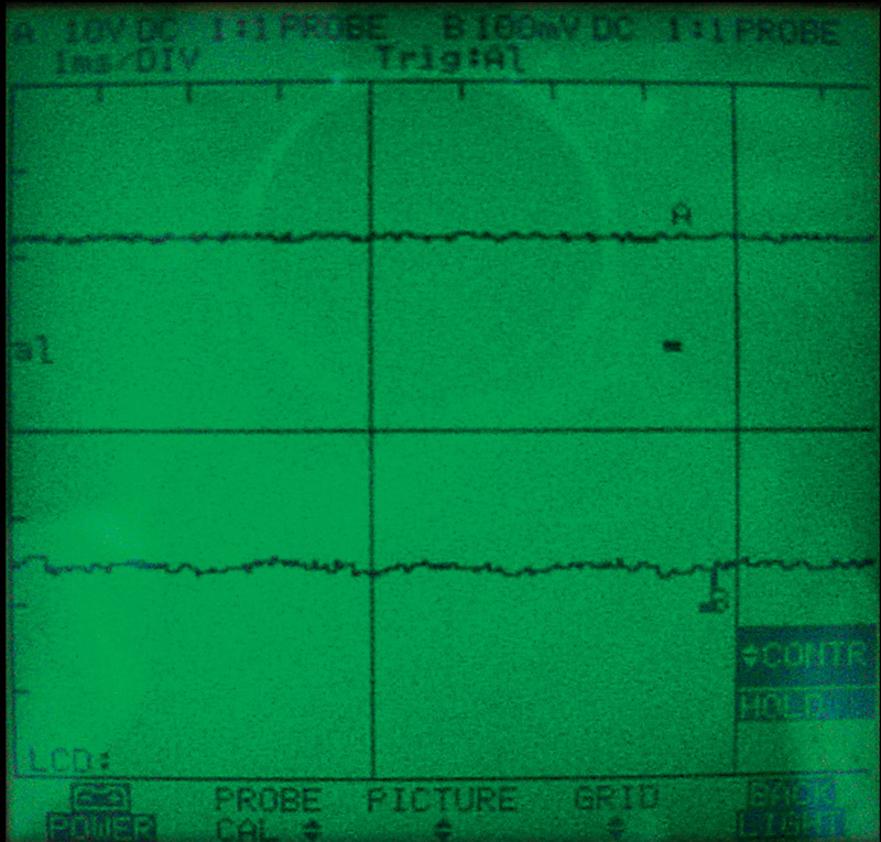
If you would like to take your diagnosis a step further, look at Figure 6. This is a scope pattern of an auxiliary coolant pump in action. Channel A (upper) is a voltage reading. This is the ground for channel A, and since the scope is set to 10 volt divisions, and the actual waveform is just over one grid block above it, we can determine the voltage is approximately 12V. Channel B (you can see the letter B just below the actual waveform) represents 0 amps. Since the setting is 100mv per amp per division, and the low current probe is set to put out 100mv per amp, you can deduce that the waveform is at about .5 amp, which was the reading when the engine was first started. You also may notice on channel B the slight humps in the current pattern as the brushes pass over the commutator. There are about five visible in this pattern, but for the most part, like the voltage pattern on Channel A, the pattern is fairly steady, meaning that this auxiliary coolant pump is functioning properly.
In Closing…
Heating systems can be simple to diagnose. Yes, there are the water pumps that are on the verge of not circulating enough coolant and yes, you may have a sticking Duo-Valve to complicate your diagnosis, but after reading this article and following the testing procedures you should be able to find any problem with the auxiliary coolant pump.




0 Comments