

Working on Controller Area Networks (CAN) may sound daunting, but here’s the information to help you understand how to service these advanced communication systems.
All 2008 and newer vehicles are required to use a digital communication system known as a Controller Area Network, or CAN. Nissan adopted this standard several years ago for some models, so some readers may already have CAN diagnostic experience. If not, don’t worry. CAN will make diagnosis easier, not harder. This article will explore the basics of CAN, and includes some diagnostic tips that should be useful regardless of your experience level.
Does CAN replace OBD II?
CAN and OBD II are two different things, so one does not replace the other; they exist together. OBD II is a standardized interface. CAN is a communication standard, available via the OBD II interface. If a car is CAN equipped, the CAN bus may be accessed through pins 6 and 14 of the OBD II connector on Nissan, Infiniti and every other make of car.
Some scan tools will not communicate with CAN vehicles because they were not designed to. The CAN bus “talks” much faster than the scan tool can “listen”. There are adaptors for some scan tools to slow the data down to an understandable speed, but this is not optimal. As always, your best choice for talking to a Nissan is the CONSULT. Not only will you be using a native speaker, fluent in CAN, but you’ll also have access to a plethora of data that was not included in the OBD II standard, but can be immensely useful when performing diagnosis.
Sharing information
Many control units need access to the same types of information. For instance, the ECM might want to know vehicle speed for its fuel calculation, the TCM for its gear selection, the BCM for its seat belt warning, the combination meter for its speed display, EPS to determine the correct amount of steering assist, the IPDM for cooling fan operation, etc. Before CAN, each control unit had to have its own information source, perhaps through its own dedicated sensor, or a splice into a sensor for another control unit or perhaps through a dedicated data line with another control unit.
The more advanced cars become, the more information they generate. Features and performance require information. The added cost and weight of each control unit having its own “department” for each type of required information was not practical.
CAN solved this dilemma by providing a means for every bus-connected control unit to share the information it gathers with other control units, as well as access information it needs from them. Thus, the vehicle speed sensor can be linked to the control unit that has the most urgent need of its data, or it could be linked to the control unit that is physically closest to reduce wiring, cost, and weight.
Fast!
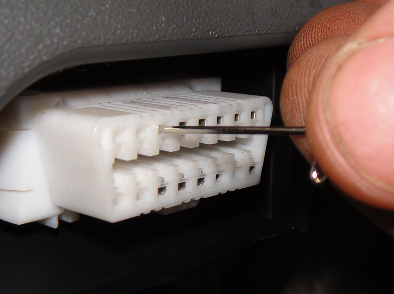 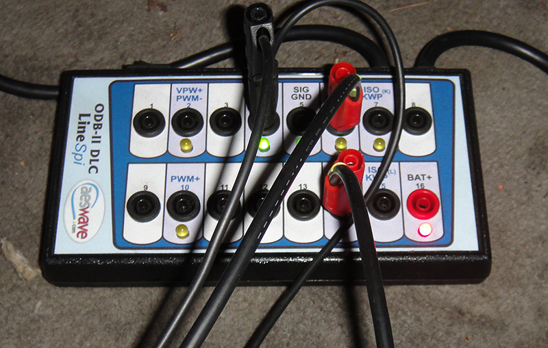 Never jam pins into the DLC! Use a breakout box or back-probe the connector. Never jam pins into the DLC! Use a breakout box or back-probe the connector. |
The economies of scale achieved by consolidating “departments” and eliminating redundancy are a big part of CAN’s value, but not the only part. Speed is another reason CAN is a necessity. Many features could not exist without the high-speed data transfer CAN provides: improved ABS and SRS, throttle-by-wire, and VDC to name a few. Data flows on the CAN bus at a rate of 1Mbit/s, or 1,000,000 bits per second. Depending on the frame format, a 0-8 bit “message” will be between 44 and 73 bits. This allows 13, 698 to 22,727 complete messages per second! To put this into perspective, a hummingbird flaps its wings “only” 35 times per second, but it’s so fast they become almost invisible to us. If each bit sent across the CAN bus made a noise, it would be about 50 times beyond the range of human hearing. How fast is CAN? Way faster than human perception!
Vehicle systems are not the only beneficiaries of CAN’s blazing speed; a technician will be able to make use of the increased throughput as well. You’ll notice that control units that communicate with the OBDII port via CAN refresh a whole lot faster, especially when a lot of PIDs are being monitored at the same time.
Physical layout
The ‘bus’ consists of a two-wire backbone, twisted together to reduce noise. Control units are teed into the bus with splices. All control units connected to the CAN bus are connected to the bus in parallel. This means that the bus does not “go through” the control units; it goes to and from the control units. Two 120 ohm terminating resistors, located inside of control units, are connected across the bus at the ends of the backbone. Usually you’ll find one of the resistors in the ECM, and the other in the IPDM. If the vehicle does not have an IPDM, the second resistor is usually in the TCM. Check the LAN section of the service manual for specifics for the vehicle you’re repairing.
What does it say on the bus?

A scope CAN trace.
All of the control units talk and listen on the same bus, so there are rules of order. Important ECUs with important jobs have priority. Other ECUs can wait for a lull. You’re not going to be able to tell what the control units are talking about without a scanner, but if you know what to expect, you’ll be able to tell if the chatter on the bus is communication or gibberish. The two wires on the CAN bus each carry their own signal: CAN H (or CAN high) and CAN L (or CAN low). It’s easy to access these wires since CAN H will always be pin 6 on the OBDII connector, and CAN L will always be pin 14 on the OBDII connector.
When silent, CAN H will stay at 2.5V, and CAN L will stay at 2.5V. If you connect one scope lead between pin 14 and ground, and the other between 6 and ground, you’ll see a steady 2.5V on both traces, provided no one starts talking.
When a control unit talks, it will raise CAN H to 3.5V, and drop CAN L to 1.5V. CAN H and CAN L move in equal and opposite directions simultaneously, which helps to reduce noise. If you watch the CAN bus with a scope, you might be able to see some things that might be useful in diagnosis. Excessive amplitude and sloppy signal is a sign of a missing terminating resistor. If CAN H or L were grounded or high, you’d notice that. Taking a peek at the CAN bus with a scope is fun, and may rarely lead to an otherwise impossible diagnosis, so by all means, take a few minutes to check it out on occasion, but you should know that it will not be your most effective diagnostic tool.
Diagnosis
CAN diagnosis is almost always going to start with a scan tool and the application of logic. A logical equation does not work unless all premises are true, so using the right equipment and information are the keys to avoiding frustration. A CONSULT is the best way to ensure the data you acquire is accurate. Nissan Techinfo is the best source for the information necessary to analyze the data you collect. Diagnosing communication problems with anything else is asking for trouble.
The first question should always be, “What’s wrong with the car?” Why did the customer come in? What problems did the customer notice, and have you noticed any additional problems? CAN allows sharing of information among many seemingly unrelated systems. This can produce some very strange combinations of symptoms. The common customer refrain of, “I think it’s something electrical,” following a long list of seemingly unrelated symptoms is more likely than it used to be.
After collecting the symptoms, see what you can find with the scanner. Are there any communication codes? Check the service manual’s CAN System Specification Chart to find out what control units should be installed.
Are they all reporting in?

CAN System Specification Chart
Nissan provides three very useful CAN diagnostic tools in the service manual:
- The CAN System Specification Chart is a tool for figuring out what you’re working on. Looking for a control unit that does not exist is a big waste of time. This chart provides a way to quickly determine what equipment your car has, and shortcut to diagnostic information that is relevant to it.
-

CAN Diagnostic Sheet.
The CAN Diagnostic Sheet is a tool used to help the technician visualize the physical layout and connections between control units.
-

CAN Communication Signal Chart
The CAN Communication Signal Chart is a tool the technician can use to figure out which control units receive a signal and which control units send a signal. For instance, a VSS signal might originate from the Unified Meter and AC amp., and be received by the ECM and TCM. This chart provides all of the send/receive relationships at a glance.
If you don’t know how it’s supposed to work, you’ll be lost while trying to diagnose it. Using these three diagnostic tools in order will help you to quickly figure out how the system should be working. Once you know that, you’re on your way to fixing it quickly.

Using an ohmmeter is an easy way to verify that the terminating resistors are OK, and that the bus is OK between the DLC and the terminating resistors.
An ohmmeter is a tool sometimes sneered at by some top-tier techs, but it is a very fast way to verify that the terminating resistors are OK, and should come out before reaching for the scope. The bus has two 120 ohm resistors wired in parallel, so the resistance measurement between pins 14 and 6 should be 60 ohms. There should be no continuity between pin 14 or 6 and ground. This is always the case on any CAN-equipped car. If you measure 60 ohms across the CAN bus, you know the bus is good at the point you are measuring. The same test can be repeated at any of the control units if there is a suspected break in the wiring.
Diagnostic pitfalls
There are a few things (well, maybe more than a few) that can occasionally be confusing. One of these is that on some cars there are control units that talk to other control units using the CAN bus, but use the K Line to talk to the DCL. This is an important tidbit if you can talk to a control unit with the scan tool, but other control units think it’s offline. Information on which units communicate to the DCL via CAN is found on the CAN Communication Signal Chart.
Another potential diagnostic challenge is determining when a problem is transient and when it’s intermittent. A transient problem occurred, but will probably never come back. An intermittent problem came and went, but will probably be back soon enough. Intermittent problems are often caused by poor connections, moisture, cracked solders, excessive heat, etc. Wiggle and tap testing are the best tools for finding intermittent problems (though sadly not always effective). Before beginning a major disassembly, look for clues of a transient problem and talk to your customer about options.
A U1000 or U1001 code will occur when communication is lost for two seconds or more. This could have been caused by something as simple as a discharged battery. If freeze-frame data is available, check for low battery voltage. Recent repair work is another possible cause of communication codes. If a control unit is unplugged while alive, it may set some codes. A reprogramming that did not complete normally may also cause communication codes.
Finally, an increasing number of aftermarket accessories are tapping into the CAN bus. If you notice an aftermarket accessory, try pulling its fuse before spending too much time on diagnosis.
Repair
The CAN bus may be repaired under some circumstances. It may be tempting to run a patch between the two control units affected by the break, rather than trying to find a break in the harness, but this is a very bad idea for several reasons. One is that any splices between the two points will be cut out of the bus, creating another problem to diagnose. Another is that a jumper will lose the benefits of the twisted pair. The patch may “sort of” work, but it may also introduce a lot of noise onto the bus, causing all sorts of intermittent problems and diagnostic headaches.
For these reasons, the only Nissan-approved methods are replacing the harness or finding and fixing the damaged area. The repair should not exceed 110 mm. The patch wires should be of similar gauge and soldered into place then sealed with tape.


0 Comments