Although Mercedes-Benz offers a hydraulic suspension system (Active Body Control, or ABC), there’s an alternative. AIRmatic suspension doesn’t need hydraulic fluid, or a belt-driven high-pressure pump to maintain a level stance. Vehicles so equipped float on a cushion of air, so how do we keep them afloat?
Ride comfort is one of the many sterling traits Mercedes-Benz is known for, especially on its flagship models such as the E-Class, S-Class, and Maybach. As touring vehicles, they can be driven on winding country roads, or on long Interstate trips with equal aplomb. Being five-passenger sedans or coupes with enough trunk space for a golf outing, the load may vary quite a bit. Conventional suspension systems either sag from the additional weight, or are sprung so stiffly that they give a harsh ride when lightly loaded. To have the best of both worlds, a suspension system that can automatically adapt to changing loads is necessary, and this is what AIRmatic offers. Steel springs have been replaced with air bellows in the strut assemblies. An electronic system measures the ride height of the vehicle and determines if air needs to be added or removed from the struts to change the height. AIRmatic comes with ADS (Active Dampening System) and also controls suspension compliance with air pressure. It accomplishes these tasks with a series of pumps, valves and lines. But what do we do in the event something goes wrong?
The Heart
The heart of the AIRmatic suspension system is the pneumatic pump. On a 220 chassis it is usually located behind the bumper, under the car, on the passenger side. In the E-Class, it’s usually mounted behind the driver’s side of the front bumper, ahead of the front tire. With an R-Class model, it is in front of the passenger side front tire, behind the bumper. It contains the pneumatic pump and a pressure-reduction solenoid, which is sometimes referred to as the vent solenoid. The pump is capable of producing over 200 psi. Your SDS will display the pressure in Bar — just remember one Bar equals 14.7 psi of air pressure. One of the tests offered in the SDS software is to run the pump for 40 seconds and verify that it can produce 205 psi. The draw of these pumps can soar to about 100 amps at start-up, and stays at around 40 while running. They are typically protected by a 40-amp fuse. In the R- and the S-Classes, the driver’s side fuse box houses the fuse and the relay for the compressor. In the E-Class, the relay is mounted separately from the fuse box, but still in the electronics housing. If you replace a compressor, it is always a good idea to change the relay since volta
ge drop across the contacts will increase the amp draw of the pump.
The pressure reduction solenoid (a.k.a. vent) is normally closed. This allows the pump to build up pressure and lift the vehicle. When the vehicle needs to be lowered after it is unloaded, this solenoid (as well as the individual shock solenoids for each corner) is commanded open to relieve the excess air pressure in the suspension. If the vent solenoid gets stuck closed, the suspension will never drop and compression dampening will get very stiff, giving the customer a harsh ride. If the vent solenoid gets stuck open, the pressure will never build up and the vehicle will not lift, so it is important to verify that it closes. You can activate the solenoid manually using the SDS or equivalent. You should see about 15 ohms on the solenoid windings and overall amperage draw of around one amp when the solenoid is activated (open to relieve pressure).
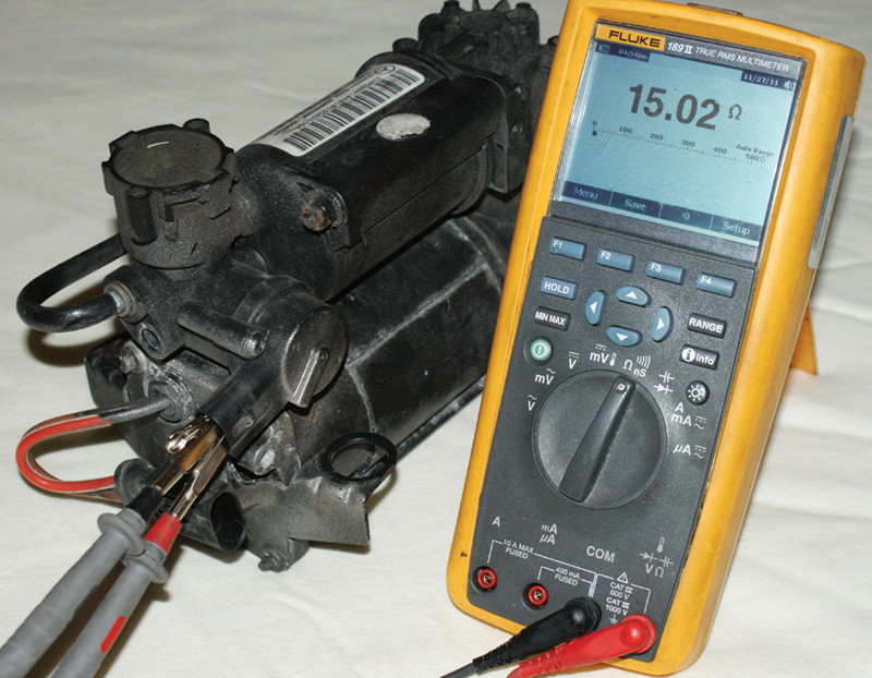
The heart of the AIRmatic system is the air pump. It includes the pressure relief solenoid, which vents overall system pressure to lower the vehicle. If you have a case of no lift, verify that the solenoid is not stuck in the open position.
Other solenoids in the system are the air dampening valve units. These are typically mounted on the individual shock or strut. They do not affect ride height, but they do control the dampening, or shock-absorbing, characteristics. Each shock assembly has two solenoids. One handles compression dampening and the other rebound dampening. Other solenoids are used to allow air into and out of the air bellows of the strut/shock assemblies. In the case of the the early 220 chassis, each shock has a single chamber to fill. On later 220 and 211 chassis, dual chamber assemblies are used (more on that later).
Air Storage And Distribution
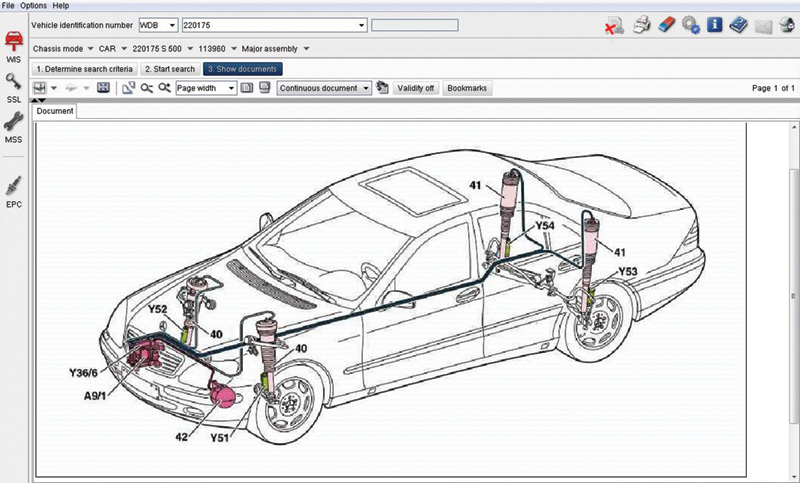
Using WIS, you can see a layout of the system. This helps isolate where you have to look for a problem. Also, safety procedures and detailed instructions are given to insure the safety of the technician.
Once pressure is created, it is collected in a central reservoir, so extra air pressure is available if needed. The charge valve controls the pressure into and out of the reservoir from and to the rest of the system. A test is available in the SDS software for this solenoid. It drops the pressure in the overall system by opening the vent solenoid, then closes it. It then opens the charge solenoid and the excess pressure is expected to increase the pressure in the system. The four corners are controlled independently, but there are some slight differences among the different chassis. On the 220 and 251 chassis, the pump and reservoir feed a valve block that distributes the air pressure to the individual strut assemblies. From there, flexible lines carry the high-psi air to each strut. A leak in any of these lines will allow each corner to drop, as will a leak in the air bellows of a strut. The 211 chassis is piped slightly differently. A manifold distributes the air through flexible lines, but each strut has its own individual solenoid to allow air in and out of the bellows. A leak in a strut here usually means a solenoid problem, or that the actual strut is leaking. Applying soapy water will allow you to pinpoint a leak, but the SDS has such good control and sensor information that it is usually not necessary.
The Brains of The Operation
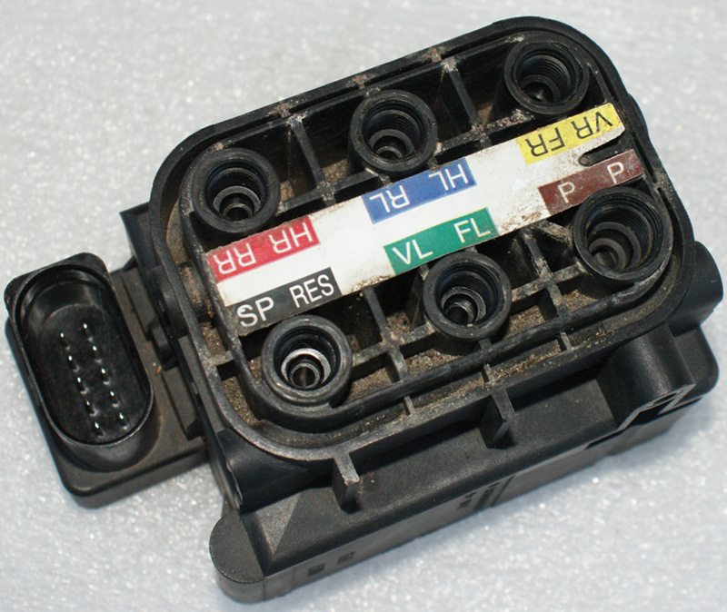
When you see this solenoid block you’ll know the air pressure sensor is incorporated into the unit. On other models, the pressure sensor is mounted in the air distribution manifold. You can see the pressure read by the sensor by using your SDS.
An AIRmatic control unit is in charge of both the level and dampening of all four corners. This is not to be confused with Mercedes-Benz’s rear level control systems with ADS, which only maintain the rear ride height and rear dampening. On the 220 chassis, you will find the control unit under the hood in the driver’s side electrical housing. With a 211 chassis, it is mounted in the passenger’s side foot-well next to the automatic transmission control unit. On a 251 chassis, it resides under the carpet in front of the passenger’s side seat. The control unit can supply power and/or ground to each of the solenoids that allow air into or out of the shock assemblies, but how does it know when to add air and when to bleed some off? For ride height correction, there are three height sensors, one for each front axle on the 220 and 211 chassis, and a single sensor for the rear axle. The sensors are of the typical three-wire Hall-effect type with a five-volt reference, signal, and ground. On the 220 and 211 chassis, four-wire sensors are used. These have an additional signal wire that shares the same five-volt reference and ground. Two body acceleration sensors are placed in the front of the vehicle, and one sensor is placed in the rear, on the right side of the vehicle, that cooperate to supply the control unit with the information it needs to manage dampening characteristics.
The body acceleration sensors are just like the yaw rate and G sensors found in ESP systems. They are three-wire sensors that also have five-volt reference, signal, and ground wiring. The signal wire of the sensor puts out just under 2.5 volts when not in motion. Depending on the sensor’s location, the signal voltage moves above and below 2.5 volts as the body pitches to the left and right during turns. Using these readings, the AIRmatic control unit can determine which dampening solenoid to activate for compression and rebound adjustments.
The only other sensor input is that of the AIRmatic pressure sensor, which reports on the overall pressure in the system. It is also a three-wire sensor with a five-volt reference, signal wire, and ground. In the 211 chassis, this is mounted in the manifold that connects the high-pressure air and the reservoir. On the 220 chassis, it is found in the valve block that controls the air flow to the strut assemblies. On the 251 chassis, it is incorporated into the valve block that directs the air to each corner’s shock. All of these sensor readings can be evaluated with the SDS software, as well as testing for each solenoid. After any work is performed on the system, the ride height will have to be recalibrated. On the SDS, look under control unit adaptations. Once you have corrected the ride height of each corner, you can recalibrate the system with the new readings.
Air Bellows
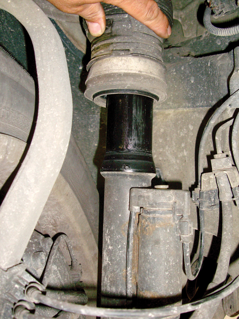
Here’s a front shock assembly on a 220 chassis that has separated and allowed air to leak out of a system. This can happen from letting a leaking system go unrepaired for some time. You can also prematurely burn out the air pump from constantly trying to fill an empty system.
If you see a comfort/sport switch on the dash, two-chamber air struts are present in the front suspension. A pair of solenoids controls each strut. One handles the pressure in and out, and the other controls the split between the two chambers. When both chambers are open to system pressure, the ride is softer due to a larger volume of air being compressed. By closing off the second chamber, the ride becomes stiffer since there is a smaller volume of air to compress. The comfort/sport switch is wired to the lower control panel and instructions are sent through CAN B. This is also how the system is awakened. If you operate a door or trunk switch, the AIRmatic system wakes up and tries to correct the vehicle level. This can be a problem if you have the system apart for repairs, so disconnect the battery after bleeding off the system.
Some Do’s And Don’ts
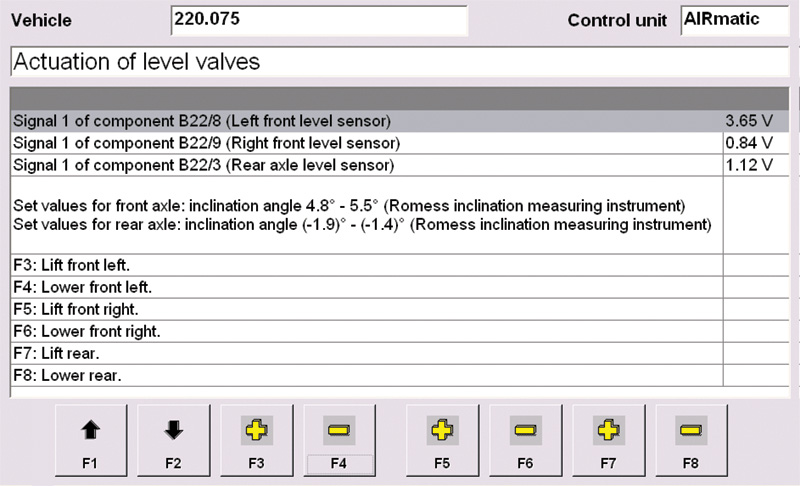
You can use your SDS to activate specific solenoids and raise and lower the vehicle. You can use the height sensor data to level the vehicle and compare ride height of each corner to that of the others.
Before attempting any repair work, vent the entire system. This should bring system pressure below three psi and make it safe to open air lines. Keep in mind when a corner of the vehicle is on the ground other parts of the system may be holding high air pressure. When repairing damaged lines, you must replace the line completely. Only the rear lines can be repaired with kits available from your Mercedes-Benz parts supplier. The rear lines must be cut if you have to remove the air spring assembly. When towing the vehicle, there are special blocks that need to be temporarily installed to support the suspension. Otherwise, the suspension may lose pressure while on the bed of the truck and allow slack in the safety straps. If you have the proper straps, anchor the wheels to the tow bed.
Knowledge of how AIRmatic works and following all of these precautions should allow you to diagnose and repair the vehicle in a manner that is safe for both the technician and the customer.


0 Comments