
To run properly, any gasoline-burning engine requires three elements to work together in perfect harmony: compression, fuel, and, our subject here, spark. Maintaining this harmony insures the legendary power and performance of Mercedes-Benz vehicles.
In any team sport, players need to work together to achieve a goal. The same applies to the internal combustion engine. The basic engine is engineered to take in and compress quantities of air. The fuel system combines a flammable liquid hydrocarbon with this air at the optimal ratio to provide a clean-burning mixture. In a diesel engine, ignition occurs naturally, so when that happens is determined by the timing of the injection event. In a gasoline engine, on the other hand, the mixture is compressed to a point where it is ready to burn, then the ignition system provides the high-voltage, low-amperage spark that ignites it. If this spark were to occur at the wrong time in the engine’s cycle, harmful emissions would increase, fuel mileage would fall, and performance would be reduced. Internal engine damage is another possibility. In the old days, we were able to adjust spark timing by twisting the distributor, or changing the gap of the ignition points. Now, of course, the computer provides vastly more precise adjustments throughout the rpm range.
The Ignition System
 is the voltage supply to the coil. You can check the resistance of the coil windings between this pin and the outer two.")
Using startekinfo.com you can pull up a wiring diagram of the ignition system, such as this one for the CLK 320. You can see that the center pin (#2) is the voltage supply to the coil. You can check the resistance of the coil windings between this pin and the outer two.
To properly diagnose ignition systems, you need to have an understanding of how they work and how they can affect drivability. The system is divided into two parts. primary and secondary. The primary side controls when spark occurs, and is sometimes referred to as the triggering mechanism. The secondary side does the actual work of igniting the mixture. It all starts in the ignition coil, which is fed voltage through the vehicle’s power distribution system. An ME (Motor Electronics) control unit, or a dedicated ignition module controls the ground side of the coil. When the coil is grounded, a magnetic field is created in and around the primary windings. The secondary windings contain many more wraps of fine wire than the primary does. When the module or computer “un-grounds” the coil, the circuit is broken and the magnetic field collapses into the secondary windings, and the result is high voltage. The ignition systems found on older vehicles before the mid-’90s had coils with single secondary towers. The spark out of this tower would be sent to a distributor cap and rotor, which would then distribute the spark to each cylinder in its turn timed to coincide with its piston approaching TDC (Top Dead Center).
How We Get kV from Just V
The induction phenomenon that generates many tens of thousands of volts at the spark plug gap from mere battery voltage is both interesting and subtle, but it’s not our purpose here to provide a detailed physics lesson. Suffice it to say that the ignition coil is actually a voltage step-up transformer. Like all transformers, it only transforms voltage from its primary windings to its secondary windings when the current flow changes. Since we’re dealing with DC, that means when the primary circuit is broken by releasing the ground. The primary has only a few windings (and thus a relatively low resistance), while the secondary has many more windings (and a higher resistance).
While the coil primary circuit is grounded (called “dwell”), the current flowing sets up a powerful magnetic field inside and around the coil. When the ground is released — changing the current flow — the energy in the magnetic field is released in the form of a higher voltage through the coil secondary. When this voltage reaches a certain level, an electrically-conductive spark forms across the spark plug electrodes. Because the spark is conductive, the voltage drops somewhat and remains relatively constant until the energy stored in the coil’s magnetic field is exhausted.
Traditionally, this has been described as “collapsing lines of flux” (meaning the primary’s electro-magnetic field) inducing high voltage in the secondary windings.
The secondary voltage must be kept high as it passes through the coil wire, distributor cap, distributor rotor, back through individual spark plug wires and finally across the spark plug gap. This high voltage, like any electrical current, is looking for the easiest path to ground. So, it will “leak out” of any component that has cracks, cuts, or carbon tracks. This means the “electromotive force” will not make it to the spark plug to ignite the mixture. The cylinder will not produce power and raw fuel will pass into the exhaust stream.
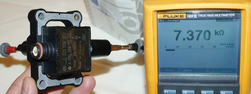
On 104 and 111 engines, the waste spark ignition system is used. A single coil serves the plugs of two cylinders, one under compression the other during the exhaust stroke. You can see here that the resistance of the secondary winding is 7,370 ohms. The primary resistance is about .25 ohm. These readings will change slightly with temperature.
This total lack of, or incomplete, combustion is called a “misfire.” On ’96 and later models, OBD II regulations require that misfires be monitored, and, if one occurs, that the MIL (Malfunction Indicator Lamp, also called the CEL for “Check Engine Light”) must flash on and off. This warning is emphasized because of the fear that unburned gasoline will overheat the catalytic converter.
Of course, for many years Mercedes-Benz has been using “COP” (Coil Over Plug) ignition, wherein there’s a small separate coil for each spark plug. This eliminates the distributor cap, rotor, and plug wires, so there is never a problem with those components. The coils themselves or their control circuitry can still fail, however.
The Basics Of Ignition Timing
It is important to know that spark does not occur at TDC. This would be too late. The piston would already be on the way down by the time the expanding gases started pushing on it. So, the air/fuel mixture is ignited just before the piston reaches the top of the compression stroke, and how much before is calculated electronically to achieve the best combination of fuel efficiency, power, and low emissions. In the past, this “advance curve” was determined on the basis of rpm by means of centrifugal weights, and engine vacuum by means of a diaphragm and lever mechanism.
Problems with Ignition
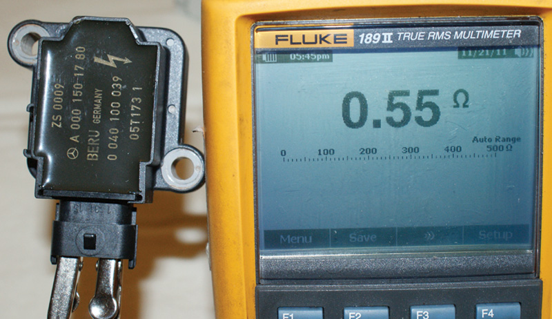
On a 119 engine, you should see a coil primary resistance of about .5 ohm between the two outer pins of the three-pin connector. The middle pin is wired to ground and is attached to the secondary windings. Verify the ground connection for the secondary windings.
As we said, if the spark occurs too late the piston will already be on the way down and power output will be reduced. If the mixture ignites too early, on the other hand, the flame front will hammer the rising piston. This will also reduce power output because what’s wanted is a smooth push, not an explosion, but it can also cause serious engine damage. This condition is known as pre-ignition, detonation, or “pinging” from the distinctive sound it makes, and it can have multiple causes. Cheap, low-octane fuel may ignite at lower combustion chamber temperatures before the spark occurs. Higher-octane fuels are more resistant to pre-ignition from heat and therefore will not ignite until the spark arrives. Also, inexpensive fuels may not burn completely leaving carbon deposits behind inside the combustion chamber. These may retain the heat of combustion and “glow,” which can ignite the incoming charge before the carefully-timed spark occurs.
Since preignition can slow down the speed of the crankshaft, it can have the same effect as misfiring in turning on the OBD II MIL, and may also cause failure of a state or local emissions test. Also, undue stress is put on the pistons, rings, connecting rods, and bearings. Multiply this by millions of revolutions and you can understand how catastrophic engine failure happens. So, the timing of the spark and the actual spark output need to be verified during the testing of any drivability problem.
Who is in Control of Timing?
When it comes to ignition timing, you need to understand that it is all computer-controlled; therefore it is difficult to test manually, and that is probably not necessary anyway. Basic ignition timing is set by a calculation of the ME control unit based on the crankshaft and camshaft position sensor signals. On earlier model engines, you may only have one crank and one cam position sensor even through you have a V8 with two banks. V12 engines usually have two six-cylinder systems mated together as System 1 and System 2. Later-model, more sophisticated engines have a position sensor for each camshaft, particularly if they also have variable valve timing. The combination of crankshaft and multiple cam sensors allows the ME unit to control ignition timing per cylinder, accurately detect misfiring cylinders, and also to test the operation of the variable valve timing system. As a result, any problem with cam and crank timing will be identified by the self-diagnostics. Other tests, such as that for engine compression, can be performed, of course.
The next largest influence on the timing calculation is that of the load sensor. Since the early ‘90s, Mercedes-Benz has used a Mass Airflow Sensor (MAF) almost exclusively to measure engine load (it is a requirement of OBD II). If the MAF changes ignition timing enough to affect drivability, you can identify the cause of the symptoms with additional testing. The additive and multiplicative fuel trim readings would also indicate there may be a problem with the MAF.
Testing The Primary

This coil is really two coils mounted in one housing. Therefore, there are two secondary windings. Short spark plug wires are used with this dual-plug system, but they still need to be checked. You don’t want to see much more than 2k ohms, or replacement is necessary.
What you will need to do to accurately diagnose a MIL-on or drivability issue is to test and verify, or eliminate, the ignition system as the source of the problem. Also, ignition can be used as a tool to identify problems present in other systems. You might perform static testing first, which is typically a matter of checking the electrical characteristics of the components. Measuring the resistance of a spark plug wire is a static test. Dynamic testing usually involves measuring the kV and amp draw of the components as you would with an ignition oscilloscope. Starting with static testing, you should always verify that you have battery voltage at the coil’s positive terminal. A quick look at a wiring diagram on www.startekinfo.com will help you identify the coil’s voltage source. Next, you can test the coil’s primary winding resistance. You could have readings from a few other coils to compare, but ideally you would use WIS (accessible through startekinfo.com) to get specifications.
Typically, Mercedes-Benz powers the coils by means of drivers in the ME control unit. You can scope the primary trigger of the coil. The way the voltage that results in the spark passes through the secondary windings affects the electrical signal of the primary, so you will see the conventional firing line, burn time, and coil oscillations. With a low-current probe, you can monitor each coil’s amp draw. The ME control unit will increase dwell with rpm, but draw is typically limited to one amp. The critical part of the signal to watch is the rate at which the amperage slopes upward. You can use other cylinders that are not misfiring as a guideline.
Testing The Secondary
The coil primary windings are only half of the equation. The resistance should be checked on the secondary side also. To do this, you will have to know how the coil is constructed. In the past twenty years, Mercedes-Benz has mainly used three designs for its ignition systems. On the older in-line four 111 engine and six-cylinder 104 engines, a coil-over-one-plug design is used with an additional coil wire going to another cylinder, which is referred to as a “waste spark” system. This coil’s secondary windings fire at both ends, one positive and one negative. There is no longer a direct connection with the positive side of the coil. Spark travels from the ground side of one spark plug electrode to the center electrode, then passes through the coil and onto the companion spark plug. In the case of the 112 and 113 engines, a single coil fires two plugs. On a 113, this happens in a single cylinder as each one has two plugs. The design is essentially two coils in one housing, sharing the same power supply. The plugs can be fired individually and are staggered to help completely burn the mixture in the cylinder. You can check secondary resistance by measuring from the output tower to its ME-controlled ground. Finally, there are engines like the 1997 119 that have one coil wire per cylinder. The secondary winding runs from the spark plug through the coil to ground, which is the center pin (brown wire) so you can check resistance across those two points.
Using the Ignition System for Troubleshooting
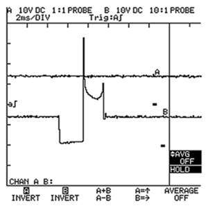
What you are looking at is the primary waveform of a 119 engine. The pattern starts off with voltage to the coil, which is then pulled to ground during the dwell period. When the ground is released, the spark line followed by a normal burn time (usually between .8 and 1.8ms) are shown. There are minimal coil oscillations from a single coil for a single cylinder.
Monitoring the coils’ secondary output kV is very important when evaluating the ignition system. You can tell exactly what is going on in that cylinder under multiple conditions. You will need an oscilloscope with an adapter for the various coil designs Mercedes-Benz uses. The first part of the pattern you will come across is the dwell, or ground time. This is when the primary circuit is complete. The next change you will see is often referred to as the firing line. This is the initial arc across the spark plug gap. A high firing line generally means the spark plug electrodes have eroded leaving a gap that is too wide, but a bad plug wire, or a lean condition can also be the cause. A relatively low firing line means the plug gap is too small, probably from physical damage, or perhaps a rich condition is present. After the firing line comes what is sometimes called “burn time.” This is the condition of the spark while the mixture is being ignited. You would like to see a smooth, flat, even line that would indicate ideal combustion. The final part of the pattern is the coil’s oscillations. These tell you if the coil is up to its task. You should see minimal oscillations with a normal coil as the excess energy in the primary winding of the coil dissipates. No oscillations can mean a shorted coil or loose connections.
Taking the few steps outlined here should help you confirm whether or not the ignition system is working properly, and isolate problems. Also, looking into the secondary ignition system is an excellent way to diagnose other troubles with either the fuel system or the basic engine mechanicals. An accurate, informed diagnosis is why your customers choose to come to you, and what’s better than that?


0 Comments