Nowhere is technological sophistication more evident than in automotive entertainment systems. These days, a Mercedes-Benz has so much more than a radio and CD player. Interconnectivity with peripherals, DVD, GPS, and Navigation make a lot of information available to the vehicle’s occupants. How do we keep this going?
People who purchase Mercedes-Benz vehicles do so because they want something exceptional. Exceptional performance, exceptional safety, and exceptional technology are only some of the reasons behind this. Nowhere is this more evident than in the entertainment and navigation systems. Engine management, ABS, stability control, etc. all have to process information at high speed to make them function as closely to real-time as possible. When it comes to media-based information systems, the needs are different. You know from you digital camera and video recorder that high-resolution files are huge. It is not critical that the information run at real-time speeds because buffers can store the information temporarily. But there is a lot of information that needs to move around. A new form of transporting this information was necessary for these systems to function the way Mercedes-Benz owners expect.
Light Speed

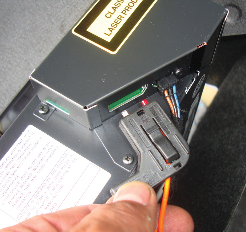
Mercedes-Benz developed its own fiber-optic network called D2B. Here is the fiber-optic connector unplugged from the unit. The red cable is always the input from the previous component, and the clear one is the output to the next component in the ring.
The answer to this digital data transfer problem is fiber-optics, which can channel large amounts of data quickly and accurately. They can operate in temperatures from -40 deg. to 85 deg. C., so they can easily withstand the interior environment of a vehicle. A fiber-optic cable can handle up to 20MB of data per second through light pulses, which must be shielded or the light will refract out of the path. Reflective cladding protects the light signal, and is also insulated with an orange outer jacket. This ensures that the pulses of light stay within the confines of the cable core.
Using a fiber-optic network has more benefits than just being able to move around large amounts of data. Light pulses are impervious to electro-magnetic interference. This means the cables can be run through the vehicle with the wiring harness and high current flow will not distort the signal. Fiber-optic cable is lighter than metal wiring and requires fewer connections. Unfortunately, fewer connections means the cables are not easily serviceable. It takes special equipment to sever a connection and re-attach it. Most of the time, it is easier to replace the entire cable rather than repair it, depending on the extent of the damage.
Mercedes-Benz implemented its version of a fiber-optic network called the Domestic Digital Bus (D2B). D2B operates the sound system, CD Changer, cellular telephone (now digital), voice recognition (if the car is so equipped), and Tele Aid control units. These features communicate with one another through an optical and electrical network. D2B transfers data at 5.6MB per second, well within the limits of the cable.
This network follows slightly different rules from the electrical networks you are used to. Most conventional CAN systems are wired in parallel with each control unit transmitting and receiving data according to priority. The D2B bus, like all fiber-optic networks, is not connected in parallel. It is connected in a “ring.” The optical signal originates from a master and is sent to the second component in the ring through the cable. A second fiber-optic cable leaves the second component and carries the signal on to the third component, and so on. The final component sends the signal back to the master to complete the ring. A complete ring is required for the D2B to function. If there is a break anywhere in the ring, none of the components will function.
Early to Bed, Early to Rise

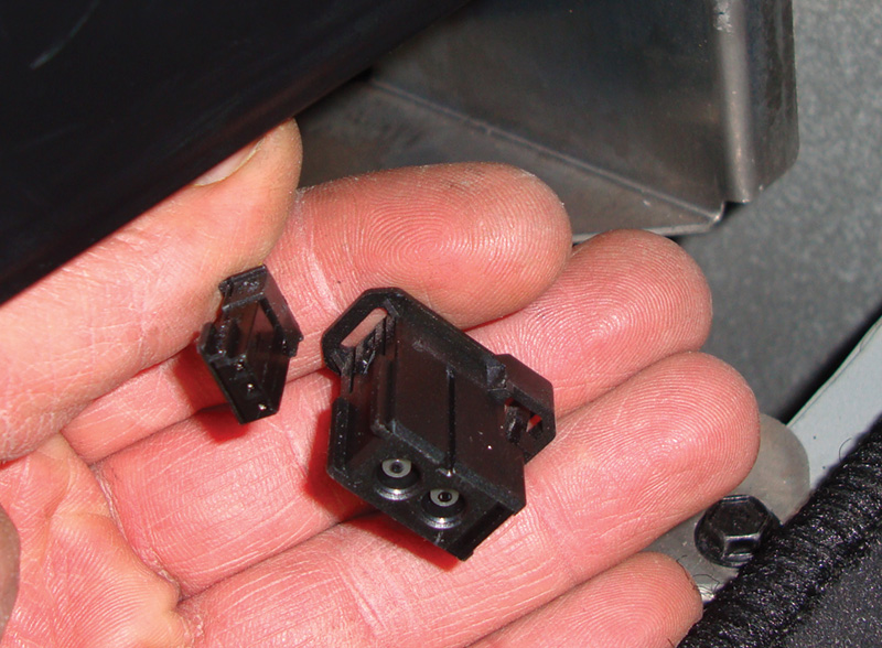
Here are two MOST connectors that plug into the CD changer. There is a three-pin electrical connector for power, ground, and wake-up signal. The two-pin plug is for the fiber-optic cable. One cable brings the light-pulse message in, and the second cable sends it out to the next component.
Fiber-optic components draw a high amount of electrical current to operate. Not only do they have to perform their function, but they also have to convert electrical signals to light pulses and send them to the next component. It also has to receive signals and interpret these light pulses coming from the previous component. When the system is shut down, each component has to be put into sleep mode. This requires a wake-up signal when the ignition key is turned on. This wake-up is achieved with both a fiber-optic signal and through the electrical star network. Each component needs to be signaled in its order in the ring. This is important when replacing or retrofitting components. When the master is coded, it is vital that each component is added in order starting from when the ring leaves the master. This will affect how the master wakes up the D2B network. If the coding is incorrect, none of the components in the system will work. On older vehicle, the master can be the radio, Command Console, or the navigation MCS unit.
In an effort to assist with self-diagnostics, both the fiber-optic network and the electrical network are not only awakened by the master, but each component also answers back on both networks. Specialized equipment is required to monitor the fiber-optic signal. Mercedes-Benz dealerships use a D2B tester manufactured by Berger Electronics. It is capable of testing the integrity of the light signal at the connector. In the absence of this tool, you can use the vehicle’s existing self-diagnostic capability to help find the problem component or cable. As mentioned earlier, the wake up signal is put out on both the fiber and electrical networks. Each control unit that wakes up sends a response signal on both networks as well. The master of the D2B monitors the response from the control units on the electrical network and compares it to the fiber-optic side. If all the control units respond on the electrical network, but only two out of five respond on the fiber-optic network, the master can determine that the failure is between components 3 and 4 or component number 3 has failed to issue a fiber-optic signal. Remember, the fiber-optic wake-up signal must have made it to components 2 and 3 because they responded on the electrical network, but could not respond on the fiber-optic. Components 4 and 5 responded on the fiber-optic network, but 3 did not. Therefore, the problem with the fiber-optic network must be between component 3 and 4.
Onward and Upward

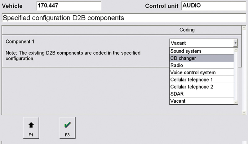
Using the SDS, you can add a CD changer in the second slot of the D2B. With the SDS, go into the audio master, which in this case is the radio, and under the retrofitting heading select the components you want to add to the fiber-optic ring. Otherwise, the audio master will not wake up the CD changer and start communicating with it.
The next evolution of the fiber-optic network is referred to as the MOST (Media Oriented System Transport) bus. The layout of the system has changed to incorporate more sophisticated electronics, but the basic structure and principles are still the same. The MOST bus incorporated a whole host of improvements. It is a standard protocol that is used by multiple manufacturers for their entertainment systems. This means a greater number of component options are available from numerous manufacturers of electronics. Mercedes-Benz started integrating this new protocol with the 211 chassis in 2003. Not all Mercedes-Benz vehicles converted to the MOST bus, but it is being added to more and more vehicles as they develop. The D2B bus was limited to a maximum of six components in the ring. With the MOST system, it currently runs about 16 components, but you can have up to 64 in the ring. Also, network speed has improved to 24.8Mbps, but can handle speeds up to 50Mbps.
A new development with the MOST bus is the watchdog function. If a component on the ring has a failure, it is possible to put that component in watchdog mode. This mode allows the malfunctioning unit to serve as a repeater and allow the optical signal to continue on and complete the ring.
On the older D2B network, the control unit head is the master of the entire network. Now, for the first generation of the MOST network an Audio Gateway Module (AGW). or an Audio 20 is in charge of all the other components. The Audio 20 is the display head in the vehicle, but the AGW can be mounted anywhere. After 2005, the second generation of the MOST bus incorporates the master back into the head unit as in the Audio 20. Either unit holds the ring configuration in its coding. This means you can retrofit or remove components from the ring as your customer desires. There are many more components on the ring, and therefore there are many more options. Like the D2B bus, the master still sends an optic and electrical wake-up signal to each component in the ring. Each component still responds back both through the fiber-optic bus and the star configuration electrical network. The master monitors the ring performance and sets self-diagnostic fault codes if problems are found. The master is also responsible for transmitting this self-diagnostic information to the other CAN networks. Your SDS does not directly connect to the MOST bus, but it can communicate with the master and access it for diagnostic purposes. The master also has many other functions.

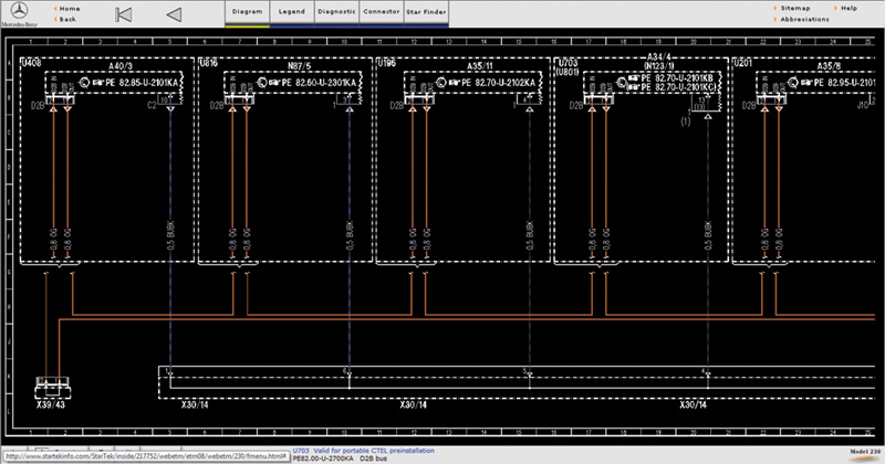
With a paid subscription to Startekinfo.com, you can access a fiber-optic cable diagram. This allows you to see the possible connections and the order the components are supposed to be in illustrated by the orange wires. The lower part of the diagram illustrates the electrical star wake-up network with the blue wiring.
Who is In Control?
The AGW has many different configurations depending on the equipment level of the vehicle. As an example, the AGW may have the sound amplifier built into it, or the vehicle may have a separate sound amplifier. If the amplifier is built into the unit, the speakers will be wired to it. It will also have the radio tuner built into it. The radio tuner is not built into the display as with the older D2B network. The head unit only functions as a display and operator interface. When the driver changes the radio station or volume through the head unit, this information is passed onto the AGW through the fiber-optic network. The electrical network is only to wake up the system, put it to sleep, and assist in self-diagnostic functions.
The AGW can be “reflashed” as changes and improvement are made to the MOST bus. If you have intermittent problems with MOST bus components, you should check for software updates under diagnostic technical bulletins on the Mercedes-Benz service website www.startekinfo.com. With a paid subscription to Startekinfo and your SDS, you can reprogram the AGW as updates become available. If the system is malfunctioning, you will still need to look at self-diagnostic information and verify that you have power and ground to any component malfunctioning on the MOST bus.
Other components on the MOST network are the Head Unit, multiple disc CD changer, navigation, satellite radio receiver, hands free module/voice control system, TeleAid including GPS, and optional external amplifier. These components are sometimes referred to as bus slaves, taking their orders from the master. All of these units are capable of putting out an electrical wake-up signal unlike the D2B network. They are also all capable of performing self-diagnosis of their own operation and report their findings to the master unit. This way, the SDS can interrogate the master for problems in the MOST bus. Within the software of the SDS and all of the components of the MOST bus is a diagnostic wake-up feature that checks the entire system. As mentioned earlier, the master and you both need to know the order of each of these slaves relative to the master unit. You can find this information by looking at the coding of the master with your SDS. Each of these components has a built-in temperature sensor. They will not function over 194 deg. F., so the MOST system may not work right away if the vehicle has been parked out in the sun where interior temperatures can get quite hot during the summer months.
How Are We Going To Fix It?
Now that you know the basic layout, function, and operation of the D2B and MOST bus networks, you will need to have a diagnostic plan if you are to proceed in a cost-effective manner. Since these systems are complicated, self-diagnostics with a capable SDS scan tool are essential to speed up troubleshooting. There are some basic steps you can perform as well. Remember, when any component fails on the fiber-optic network the entire network goes down. You need to know all of the different components in the vehicle, but if they are not communicating then you cannot use the SDS to tell you the layout of the ring. You can get a fiber-optic diagram in the ETM on Startekinfo.com.
You should start off by quickly checking the power supply to the D2B or MOST master. Checking fuses first makes sense. The next step would be to see if the master is transmitting data on the fiber-optic network. You can physically go to the next component on the list and unplug the fiber-optic connector. Look at the connector and turn on the ignition key.
In the case of the D2B network, the master attempts to start the ring up to four times. This means you should see four light pulses at the second component in the ring. Once you have verified this you can move onto the next component and perform the same test. Move onto the next component until you no longer see the red light pulse at the connector. This means either the fiber-optic cable is damaged, the component it is coming from has failed or has lost its power or ground supply. In the case of the MOST bus, the ring start from the master is nine pulses of red light. Move onto the next component in the ring and recheck the optical start signal. Obviously, since there are many more components in the MOST network this can be quite time-consuming, which is why the SDS is such an invaluable tool when diagnosing MOST bus problems. There are two special tools available from Mercedes-Benz to bypass components in both the D2B and MOST networks. These bypass connectors plug into the fiber-optic plug of the component you want to bypass. This will keep the ring complete and allow it to function without the bad component. If you find you have a problem with the electrical bus, you can unplug the buss bar that links this network together and test each wire individually for a short to power or ground, or an open circuit.
Although the D2B and MOST bus systems are technologically advanced, understanding the basic layout of a fiber-optic network and the electrical network that supports it will help you isolate problems . If you use your SDS, you can reduce your diagnostic time and come up with a more accurate answer.


0 Comments