

Before Continuous Valve Timing Systems, engineers had to make a choice – optimize valve timing for a smooth efficient idle; optimize for top end power; or, most often, compromise somewhere in the middle, losing some efficiency on both ends.
The Continuous Valve Timing System (CVTCS) helps engines breathe easy, regardless of rpm and load.. It’s one of the many ways Nissan engineers are still squeezing additional performance from four-cycle internal combustion engines, a design that has been continuously improved upon for over 140 years.
When speaking about camshaft design, there are three primary variables: valve timing, duration, and lift. Valve timing, simply put, is when a valve begins to open. Duration is how long a valve stays open, and Lift is how much a valve opens. Duration and lift are affected only by the shape of the cam lobe in most engine designs. Timing is affected by the synchronization of the camshaft and crankshaft. In other words, the rotational position of the cam in relation to that of the crank.
The crankshaft and camshaft are typically connected to each other using a timing chain or cogged belt so their positional relationship is always maintained. The camshaft sprockets are twice the size of the crankshaft sprocket, so they turn at half the crankshaft’s speed. The camshaft will spin 360 degrees (one revolution) for every 720 degrees (two revolutions) the crankshaft spins. Therefore, each valve will open only once during two crankshaft rotations.
The crankshaft’s role is to convert the reciprocating (up and down) motion of the pistons traveling in the cylinders to rotational (circular) motion that eventually will be used to power the wheels and move the car down the road. In a four-stroke engine, the piston is not performing the same function on every run up and down the cylinder.
Magnet retarder advance must be learned if the ECM is replaced.Most engines employ CVTCS on the intake cam only. Changing intake valve timing has the most benefit for efficiency — the biggest bang for the buck. However, some newer engines such as the VK50VE, VQ35HR, and VQ35DE, also have variable exhaust valve timing. It’s important to note that the exhaust valve timing control must be learned, so if the ECM is replaced or the magnet retarder is disconnected, check the service manual for the procedure. Using the CONSULT, there is a simple “wizard” style interface in the Work Support section.  Consult III plus |
Typically, the four-stroke cycle is described as starting with the intake stroke, but when speaking about valve timing, it’s much easier to start with the power stroke. The reason is that valve overlap, a key event we’ll discuss in detail later, is moved to the center of the cycle. Let’s review the four-stroke cycle:
Combustion/Power Stroke
- 0-180 degrees crankshaft rotation – the burning and rapid expansionof air and fuel pushes the piston from TDC to BDC.
- 0-90 degrees camshaft rotation – the camshaft lobes are facing away from the lifter and the valve springs hold the valves closed; the combustion chamber is sealed.
Exhaust Stroke
- 180-360 degrees crankshaft rotation – the piston travels front BDC to TDC.
- 90-180 degrees camshaft rotation – the exhaust valve is opened, allowing the spent charge to escape from the combustion chamber.
Intake Stroke
- 360-540 degrees crankshaft rotation – the piston travels from TDC to BDC.
- 180-270 degrees camshaft rotation – the intake valve opens, allowing a fresh charge of air and fuel to fill the cylinder.
Compression Stroke
- 540-720 degrees crankshaft rotation – the piston travels from BDC to TDC.
- 270-360 degrees camshaft rotation – the valves are closed and the air/fuel mixture is compressed.
Some of you may be thinking the camshaft timing doesn’t sound quite right, and you are correct. The valves do not open and close exactly at TDC and BDC. The exhaust opens a little before BDC on the compression stroke, and closes a little after TDC on the exhaust stroke. The intake opens a little before TDC on the exhaust stroke and closes a little after TDC on the compression stroke.
Inertia is the reason engines are not designed with the valve timing square with the piston movement. Once in motion, even light stuff like gasses and vapors tend to stay in motion. Good valve timing design seeks to “go with the flow.” Here’s the tricky part: the weight and velocity of the flow will change with rpm and throttle opening, as will the event time available within a cycle.
Valve overlap is the period when both the intake and exhaust valves are open at the same time. Valve overlap should be tailored to accommodate the velocity and weight of the intake and exhaust charges. If an engine is spinning at 700 rpm, the intake stroke will last about .021 seconds. If an engine is spinning at 7,000 rpm, the intake stroke will last about .0085 seconds, less than half as long. The volume of air that can flow through the valves is fixed, so to add more charge, the valve must be opened for a longer time. Therefore, the intake valve should open earlier for efficient cylinder filling at higher rpm.
But if the intake valve is opened earlier, won’t the piston still be coming up and cause flow in the wrong direction? Yes, the piston is still coming up. However, due to the inertia of charge, the piston’s push-back will not halt the momentum of the flow and the earlier valve opening will result in a larger charge and better efficiency. The optimal valve timing for an engine idling at 700 rpm will be very different from that for the same engine screaming down the freeway at WOT and 7,000 rpm.
CVTCS changes the relationship between the cam sprocket and the camshaft. To advance the cam timing, the sprocket rotates the camshaft in the same direction as the cam is turning. To retard the cam timing, the sprocket rotates the camshaft in the opposite the direction.
CVTCS most often uses hydraulic control to operate the sprocket, although some engines use an electromagnetic retarder on the exhaust cam. Before an engine is started, there is no oil pressure available. Therefore, all hydraulically actuated cam sprockets use a spring activated locking pin to hold the cam in the fully retarded position when there is no oil pressure. This can be useful to remember when diagnosing CVTCS systems. Oil pressure is necessary to advance the cam timing. If there is no oil pressure, the intake camshaft will not advance.
Hydraulically-actuated sprockets use vanes and oil chambers to control the cam timing. The outer portion of the sprocket has chambers. The inner portion of the sprocket has vanes with wipers sealing it to the outer sprocket’s chambers. The inner portion of the sprocket will rotate as oil pressure is applied on one side of the vane and is released on the other.
The IVT (Intake Valve Control) solenoid controls the application of pressure to the chambers in the sprocket. The solenoid valve is duty-cycle controlled by the ECM. By varying the duty-cycle and thus the position of the IVT solenoid spool valve, the timing can be advanced or retarded by applying and releasing pressure on opposite sides of the vane, or locked in place by centering the solenoid valve with approximately a 50% duty-cycle and blocking off the inlet and outlet ports.
The crankshaft position is monitored by the CKP (Crankshaft Position) sensor, also referred to as POS. The camshaft is monitored by the CMP (Camshaft Position) sensor, also referred to as PHASE. Both sensors are typically magnetic Hall Effect type, and generate a square wave as reluctor teeth spinning with the cam and crank pass the sensor. The CKP sensor indicates crank speed with pulses at regular intervals, and position with an irregular pulse at TDC. The CMP sensor indicates camshaft position using a unique pattern to identify each cylinder’s valve events. It’s important to note that the PHASE is based on actual cam position after timing modification, not sprocket position. Information from the CKP and CMP is reported to the ECM, creating a feedback loop. The ECM adjusts, checks position, and adjusts again, thus: Continuous Valve Timing Control System.
In order to determine the most appropriate intake valve timing, the ECM will typically monitor the following inputs:
- Engine Speed
- Throttle position
- Coolant and/or oil temperature
- Vehicle Speed
That about covers the basics of how CVTCS works, now let’s take a looks at why it can stop working.
The Number One cause of CVTCS failure is lack of oil maintenance. Low oil, oil contamination, oil degradation – almost all CVTCS failures are related to motor oil, or lack thereof. Obviously, if the oil pump is spewing compressible oil foam instead of liquid oil, hydraulic control cannot function, so oil level is very important. The IVT control valves have very little clearance and it doesn’t take much debris or grit to cause them to bind. Even severely degraded motor oil can cause sticking.
P0011 and P0021 Codes
Luckily, most Nissan vehicles with CVTCS have both circuit and rational self-tests to aid in diagnosis. P0011 and P0021 are codes based on rational testing. The CKP and CMP sensor output is compared to the IVT solenoid command. Based on the comparison, the ECM determines whether or not the CVTCS is working, and can set a P0011 if BANK 1 performance is poor or a P0021 if BANK 2 performance is poor.
Start by looking at things through the ECM’s eyes: the data list. Take a look at what the ECM is commanding and seeing. The INT/V TIM B1 & B2 PIDs indicate the calculated camshaft phase angle based on the CKP and CMP sensors. The INT/V SOL % is an indication of the IVT solenoid duty-cycle. You may or may not be able to find a cam angle request PID, but you can get an idea of what’s happening by comparing the CA° with the SOL%. Sadly, the SOL% will not be exactly 50% when holding, but you should find that it rests at a fixed number when the cam angle is not changing. If the INT/V SOL % is less than this angle, it’s a retarding command, if more, it’s an advancing command.
P0075 and P0081 IVT Solenoid Circuit Fault Codes.
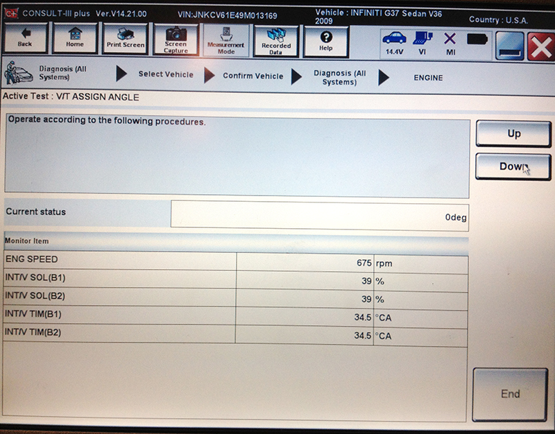 0 Degree Active Test |
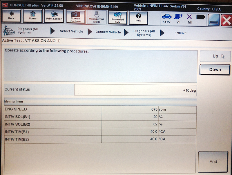 10 Degree Active Test |
| There is also a CONSULT Active Test available on some models that allows you to change the cam angle command while watching the INT/V TIM PIDs. |
The ECM monitors voltage on the IVT solenoid control wire, then using the known resistance of the IVT solenoid, engages Ohm’s Law to infer circuit amperage while operating the solenoid. The most common cause of these codes is unplugged connectors, so start by looking up locations (if necessary) and visually inspecting. If there are no obviously disconnected components, there are numerous ways to test the circuit, including the easy tests outlined in the service manual. However, checking circuit voltage and amperage with an oscilloscope will yield the most information in the quickest possible way. Note: If the ECM is not commanding the solenoid, be sure to clear the codes and check solenoid resistance before jumping to any conclusions. The ECM may stop attempting to command a solenoid when there is a known problem. Overload the driver once, shame on the solenoid. Overload the driver twice, shame on the ECU.
CVTCS-Related Problems
We’ve now covered what CVTCS does, the theory behind it, the electrical, hydraulic, and mechanical components involved with CVTCS and their functions, and a bit of the self-diagnostic logic that monitors the system function. Now let’s take a look at a few CVTCS-related problems that might roll through your shop’s door:
The idle is smooth, but power over 3,500 rpm is poor
This is the most common symptom when the cam timing is fixed in the retarded position. Valve overlap is minimal, which is great for a smooth idle, but awful for higher rpm output. There could be a problem with the IVT solenoid winding or wiring, coupled with a MIL and P0075 or P0081 (IVT solenoid codes). Or, there could be a mechanical problem with the IVT solenoid or the camshaft sprocket coupled with a P0011 or P0012.
The idle is rough but the engine runs great at higher rpm
As you might have guessed, the cam timing may be advanced all the time. Valve overlap is too high at idle and there is not much inertia to the slow-moving intake and exhaust charges to keep things flowing in the right direction while both valves are open. Poor cylinder filling and charge dilution prevent efficient combustion at idle. You might find P0011 or P0012 codes, or misfire codes.
Misfire codes on cylinders 1, 3, and 5 (BANK 1)
There are only so many things that will affect all of the cylinders on one bank but not the other, and most of them are pretty exotic. Poorly cast aftermarket exhaust manifolds (it happens!), an unusual vacuum leak, maybe wiring for an injector rail. However, before looking to the exotic causes, check the basics.
In this case, cam timing would be Suspect #1. Remember that on vehicles with CVTCS, the timing marks may line up, even though the actual intake cam timing is 30° off. The CONSULT is usually the quickest way to check cam timing, followed by using an oscilloscope to check timing with the CMP sensors and CKP sensor. If you’re old-school, and want to reach for your degree wheel and dial indicators, remember that the CVTCS needs oil pressure to operate, and there will be no pressure when the engine isn’t running.
The engine seems to run fine, but there are CVTCS codes stored in the ECM
Check the oil first! You’ll notice that one of the first steps in the service manual diagnostic tree is to check the oil pressure warning light. As you likely know, low oil level usually doesn’t cause a solid dash indicator, at least not at first. The oil light will momentarily flash on while braking or cornering as the oil in the pan sloshes away from the pickup in the bottom of the pan. A test drive to a curving freeway on-ramp might duplicate the conditions that caused the code, but recommending an oil change might be a quicker way to deal with the situation. There is no need for diagnostic heroics until the basics, like having oil in the engine, are addressed and eliminated as a possible source of the issue.


0 Comments