

Diagnosing and servicing power door lock problems is not an everyday task, but knowing how to handle such issues when they arise will make your life a lot easier.
There are many features in today’s door lock systems. It’s rare indeed to see a simple system with only switches and actuators. Most modern cars have keyless entry at minimum, but more often than not there are also programmable features such as allowing the user to select how the lock system responds to commands from the remote, or shifter range selection. Some even have the Intelligent Key System (IKS), a hyper-functional vehicle entry and security system that requires virtually no extraneous input from the driver.
All this automation is made possible with electronic control units bantering in binary, a language you can “listen to” with an oscilloscope, but can’t understand without the help of a CONSULT to translate. Some 1s and 0s travel over copper, and others fly through the air in wireless bursts. Diagnosing a power door lock problem may seem daunting due to the level of system complexity, but not to worry, basic electrical and electronic skills and the ability to find information on the Nissan Techinfo websites (www.nissan-techinfo.com) is all that’s necessary for success.
The “key” to door lock diagnosis is focusing your efforts on only one small section of the system. The system is too large to test every component and wire. It would take too much time and be very inefficient. However, if the system is broken down into manageable segments, it’s easier to have a full understanding of the segment under test, and it’s less likely you’ll get confused. A complex electronic system is made up of simple circuits, and simple circuits are easy to diagnose with basic electrical skills. Any electrical system, no matter how complex, can be diagnosed with fundamental electrical knowledge, provided it’s broken down into bite-sized chunks.
So, where should testing start? Where the problem is, of course! But, where’s the problem?

CONSULT Active Tests can be used to command door lock functions.
Start with a broad investigation before reaching for tools or test equipment. This process can be broken into five sections:
- Find out how the system is supposed to work.
- See which parts of the system are working, and which are not.
- Search for TSBs.
- Look for segments of the system that might cause all of the symptoms and eliminate those that cannot account for the symptoms or can be verified to work based on other functionality.
- Check the wiring diagram and component locations, then plan your attack.
Find out how the system is supposed to work. That owner’s manual in the glove box is a great resource for a technician. No one can be expected to know every feature on every model. It’s too much information to retain. However, a good technician should be able to find information quickly. Learning the formatting used in owner’s and service manuals is a valuable skill. There’s no reason to paw the car owner’s copy with your greasy mitts; the owner’s manual is available online, in a searchable PDF format.
Once you know how the locks should work, test every function. Mentally note what works and what doesn’t. Spending a few minutes pretending to be the owner and trying every possible combination of things he or she might do is often the most productive step in diagnosis.
Use the CONSULT to help narrow your focus. You may be surprised at the level of body control data and bi-directional control available in the CONSULT, even on older vehicles. The ability to check every door switch, lock button switch, remote command, latch switch, without pinning out the body control module saves hours. Save component and circuit testing for confirming an illogical signal with the CONSULT.
Search for TSBs
Some of you are proud technicians, with a long track record of accurate diagnosis of challenging problems. However, don’t let pride prevent you from using ALL available resources. TSBs can lead you right to the necessary tests and this can save hours of diagnostic time. Look at the answers before doing the work. Reserve your diagnostic prowess for occasions when there isn’t a ready-made solution.
If there isn’t a TSB, then it’s time to put on your thinking cap. Start with the missing output(s). For instance, if the right rear door lock does not cycle with the others on a 2005 Altima, all of the other door lock functions are normal, and there are no seemingly abnormal inputs to the BCM, the next step is to do some research in the service manual.
The door lock section starts with component locations, including fuses. This is good information that will save time during testing, but we’re not ready for testing yet. Next, is a system description and simplified schematic. If you read the description while looking at the schematic, you’ll quickly be able to learn how the system should work.
The driver’s door lock cylinder can be unlocked separately from the other three doors. The BCM uses three terminals to power the door lock actuators. One terminal is connected to all four actuators in parallel. The next is connected to just the driver’s actuator. And the final is connected to the three other actuators in parallel. In other words, the BCM is capable of locking all four doors, unlocking just the driver’s door, and unlocking the other three doors.
In the 2005 Altima example car, only the right rear door lock actuator does not work, therefore we can eliminate the BCM as a possible cause because a problem with the BCM could only affect all actuators, or just the driver’s, or all three of the passenger actuators. There is no separate fuse for the RR door actuator, so there’s no point in checking fuses. In this case, the best place to start testing is the right rear door.
Back to the manual for more information: First, find out how to remove the right rear door panel if you’re not familiar with the procedure. It’s better to spend a couple minutes to review the procedure than couple days waiting for a replacement for something broken during disassembly. Next, the schematic was a good source for an overview of the system, but the wiring diagram contains the detailed information you need, like wire colors, and connector information.

Use the manual to find hidden screws to avoid breaking something.
In the case of our 2005 Altima (and most cars), each of the door lock actuators has a two-pin connector and the actuator is not grounded to the chassis. When power and ground are applied to an actuator, current flows through a winding and a magnetic field is created. The magnetic field will push or pull an armature to move linkage and either lock or unlock the door. The polarity of the current flow determines the direction of the armature movement. In other words, if you check voltage between the two actuator pins while using the door lock switch, you’d expect to see momentary voltage in both switch positions, but there should be negative voltage in one direction and positive in the other.
Because the actuator is not grounded to the chassis, power should always be checked between the two pins, not between one of the pins and chassis ground. It is of course possible to use a chassis ground for testing, but it would require two separate test lead configurations and four tests, whereas checking the between the two pins requires only one lead configuration and two tests. Every lead change and retest introduces the possibility of a testing error or a change in circuit performance. It makes sense to “see” as much as you can with every setup and test.
The best way to test a circuit or its components is almost always as a complete live circuit using a voltmeter or oscilloscope. In other words, nothing should be disconnected or unplugged from the circuit and the circuit should be energized during the testing. Voltage readings without a load on the circuit are meaningless, since voltage drop only exists when current is flowing, and current cannot flow with circuit segments disconnected. The best results will be obtained by leaving everything plugged in while testing an active circuit.
An ohmmeter is also a poor diagnostic choice. A circuit problem might be found with and ohmmeter, but then again, it might not. An ohmmeter produces such a small amount of current that even a tenuous connection might easily pass a resistance test. A poor connection, bad switches, failing windings, or mechanical problems may all look rosy through the eyes of an ohmmeter, but fail in operation under normal load.
Powering the actuator with jumpers or a power probe is also a bad technique. The circuit is built to provide power and ground to the actuator, adding your own power source is superfluous and could potentially damage the car if done incorrectly.
If we remove the right rear door panel and check for power and ground at the two pin actuator connector while operating the lock switch or remote, there are only a few possible outcomes:
- The actuator is receiving sufficient power, but is not operating – the actuator is bad.
- The actuator is not receiving sufficient power – there is a break in the wiring.
- The actuator is being powered, and is operating, but the linkage is either bound or disconnected – the linkage needs to be repaired.

Wiring diagrams contain more detail than schematics. Schematics provide a quick conceptual overview, whereas diagrams include information like wire color, connectors, and terminal numbers.
Intermittent Irritations
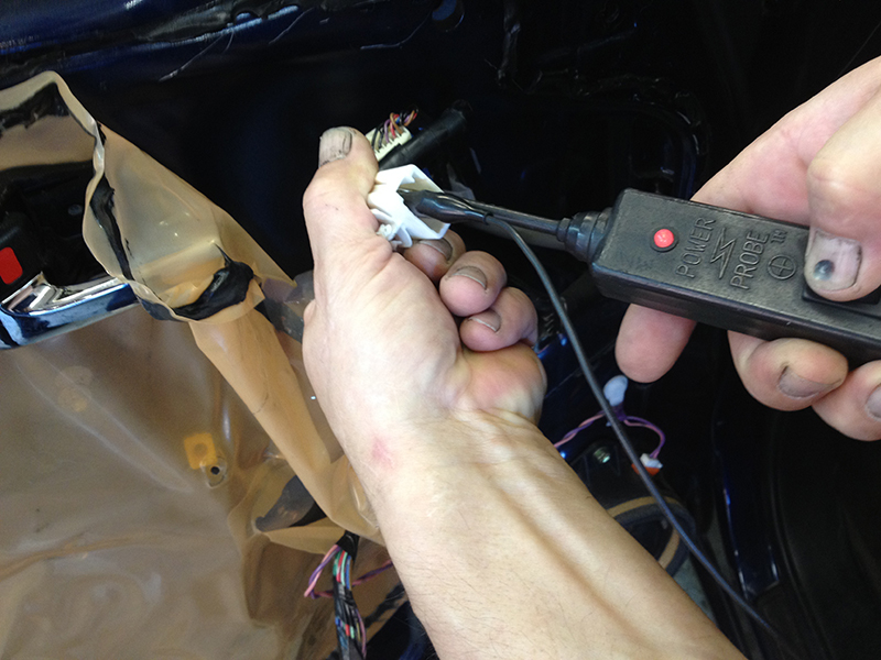
Jumpers and power probes are unnecessary and can cause damage.
Sadly, cars do not always cooperate when they come to the shop. A customer may complain of a door lock not cycling, but it works fine when you try it. It can be frustrating, but with a few tricks, you will probably be able to recreate the symptom and diagnose the problem. There are a couple of common failures that are easy to induce.
First, the winding in the door lock actuator may fail when hot. The hotter the winding gets, the higher its electrical resistance will become. If the winding’s resistance is borderline high, it may fail to cycle once warm because the higher the resistance of the solenoid windings, the lower the current flow through the coil; the lower the current flow, the weaker the magnetic field. It’s easy to heat an actuator up — just cycle the locks repeatedly. If there’s a weak actuator in the bunch, it will usually stop cycling fairly quickly.
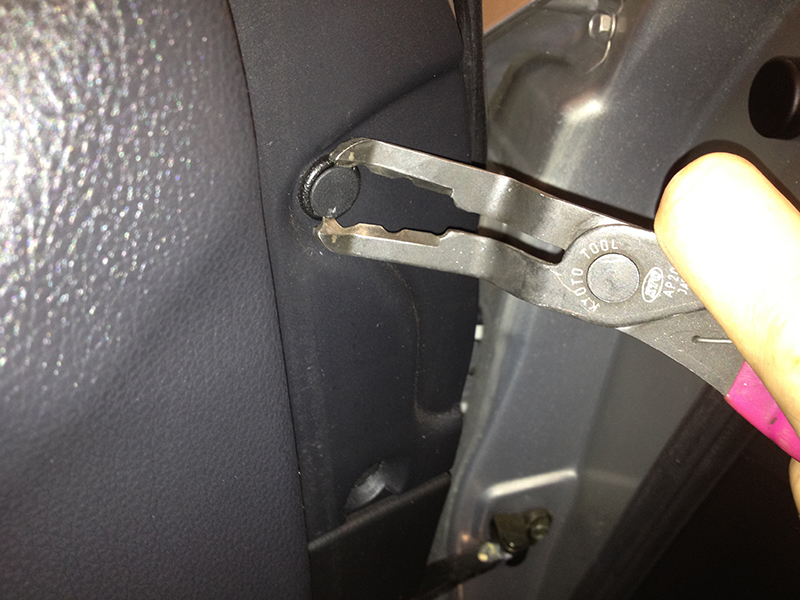
Using the correct tool saves time, aggravation, and prevents damage.
The other common intermittent failure is a break in the door wiring at the flex joint. The driver’s door is the most likely to develop this, or any problem really, because it is the most-often used door. The driver’s door lock is always cycled when the power locks are used, and the driver’s door is always opened when the car is used. The driver’s door actuator and wiring get way more use than the other doors. This is considered during design, of course, but regular use causes wear, and anything, no matter how solidly (or flexibly) built, will wear out eventually.
A great way to test door wiring is to palpate it while cycling the locks. If you can cause the lock to stop and start cycling by manipulating the flex conduit at the hinge, find out what signal is being lost, then check for broken wiring. A voltage drop test can be used to find a wire with a break or a tenuous connection, but it’s not as satisfying as grabbing the wire on either side of the suspected break and pulling hard. Unless you spend too much time at the gym, a good wire cannot be stretched, but a wire with a break will stretch and snap.
Once the problem has been found and repaired, put the car back together as well or better than it was when it came in. It’s not uncommon to find butchered vapor barriers, broken trim clips, stripped screw holes, and broken connector clips and harness retainers. Be part of the solution, not part of the problem. Fix or replace all damaged components, whether the damage happened during your encounter with the car, or was caused by the last guy. Pretend someone will be disassembling the door and evaluating your work; let their praise for the quality of your work be your reward. A flat-rate attitude may result in short-term monetary gain. However, commitment to doing quality work pays in sense of pride and purpose, and in the long run, a good reputation and advancement.
One problem with speedy communication and processing systems is, well, their speed. When viewing a list of body control PIDs on the CONSULT, switches may cycle so quickly that it’s impossible to tell what happened when. If you are monitoring 12 body inputs and outputs, and they all change within a second, how can you tell what happened? Using the graphing function on the CONSULT will allow you to see what happened first, and evaluate what the BCM is evaluating at a speed a human eye and brain can handle. Older processing systems may have required a signal to go low for >500ms to count as a switch. A newer controller may only need to see >50ms to see a switch. Linkage adjustment, inertia, and “bounce” on switch monitored parts can create some really weird door lock symptoms. Using the CONSULT or a digital oscilloscope may be the only way to find out what’s really happening.


0 Comments