When customers experience drivability problems, it is our job to isolate the cause. With systems changing all the time, we must keep pace. Even something as simple as fuel supply has had updates and changes that we need to be aware of.
The first successful electronic fuel injection system on a production car was introduced by Volkswagen on the Type 3 back in 1968 — that’s 46 years ago! Called D-Jetronic (the “D” stands for “Druck,” German for “vacuum”), it was not very sophisticated by today’s standards, but it ushered in many basics that are still used in modern vehicles. For example, its fuel supply system was based on an electric pump, not a camshaft-driven mechanical diaphragm pump as was used on carbureted engines.
Electric fuel pumps don’t have it easy. They run continuously at a wide range of temperatures, and have to tolerate both any particles that get past the pickup screen and the ethanol found in much of today’s gasoline. But the evaporative emissions system (EVAP) self-testing of OBD II regulations adds another difficulty: the temperature of the fuel can affect whether or not the monitor passes or fails. This has resulted in the necessity of Volkswagen updating its fuel supply system designs to keep pace.
New Complications
On older EFI systems, the gasoline was pumped from the tank to the injector rail, and the pressure regulator would bleed off the excess fuel and return it to the tank. As a result of this looped flow, the fuel was warmed as it passed through the lines that ran along the hot engine, thus raising the temperature in the tank. This increased the vapor pressure, making it more difficult for OBD II to calculate whether or not the system is leaking.
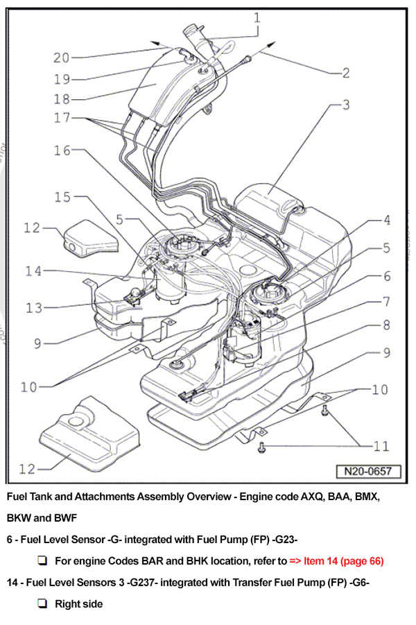
Another factor that forced fuel supply system design changes was the adoption of “saddle” type gas-tanks to accommodate a driveshaft, in Volkswagen’s case on 4-Wheel Drive/All-Wheel Drive SUVs and cars. This introduced the complication of transferring gasoline from one side of the tank to the other.
There are various ways engineers can address these design challenges. On later-model Volkswagen vehicles such as the Touareg, they chose to place the transfer pump on the passenger’s side of the fuel tank, and the main system pump on the driver’s side. Experienced technicians may remember the old CIS (Continuous Injection System — also called Bosch K-Jetronic), which sometimes included a transfer pump depending on the model, but its function was different. On those older vehicles, the transfer pump was mounted inside the tank, and the main pump that supplied the injectors was mounted on the outside. They were different pumps with different jobs. The in-tank pump was a low-pressure, high-volume design, while the external pump generated sufficient pressure to keep the injectors spraying. The in-tank pump was only there to make sure the main pump got an uninterrupted supply of gasoline, thus preventing the cavitation that would result in driveability problems.
Main Pump & Transfer Pump
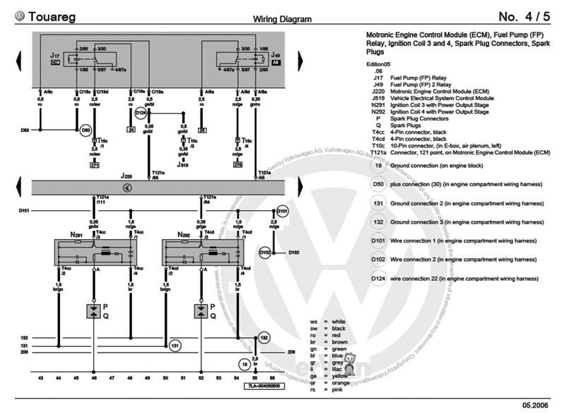
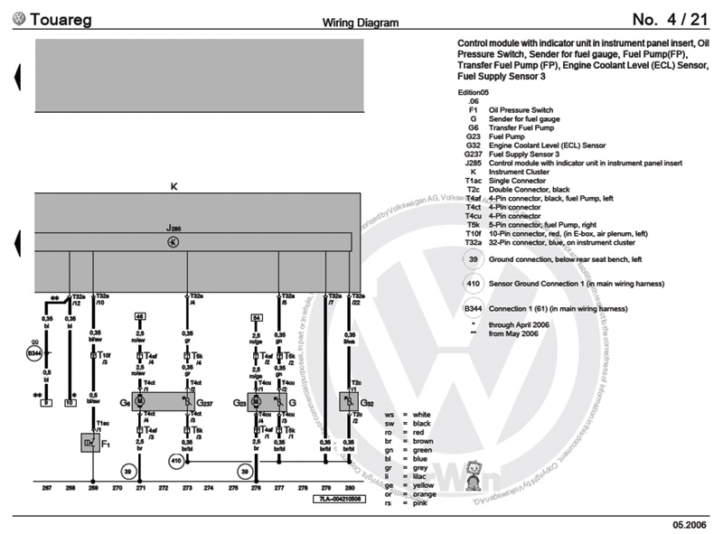
With modern Volkswagens, such as the Touareg already mentioned, the fuel the transfer pump supplies from the passenger’s side of the tank is routed through the main system pump on the driver’s side, and continues on to the engine through the same fuel lines. This is a returnless system — pressure regulation happens in the pump module. The driver’s side main fuel pump supplies the fuel injection rail. Both pumps can put out sufficient pressure and volume to run the engine, which can make diagnostics a bit tricky. If either pump stops working properly, the driver may not notice. When the engine is first started the PCM (Powertrain Control Module) activates both fuel pump relays, so both pumps begin generating pressure. These relays are mounted in the electrical power distribution center in the engine compartment on the driver’s side along with the fuel system fuses.
The auxiliary fuel pump is energized for about 30 seconds after start-up, then it is shut off and the engine should continue to run on the main pump. If the main pump fails to operate for some reason, the engine can still start on the pressure supplied by the auxiliary pump, but will stall after 30 seconds or so when the PCM de-energizes that pump.
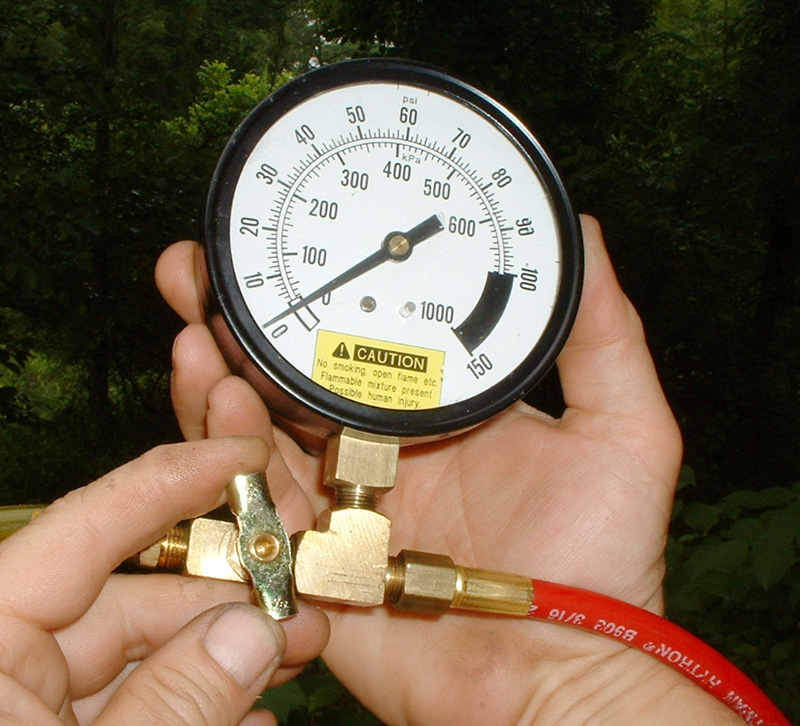
Under “Activations” on your VAG 5052, you can activate the fuel pump relays. You can connect a fuel pressure gauge to the injector rail during the activation to find out how many psi are being generated. Activate each pump’s relay individually to verify that both can provide sufficient pressure to run the engine.
Testing
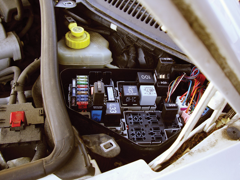
If you do not have a VAG 5052 or equivalent, you can go directly to the fuel pump relays and fuses and test the pumps electrically. As mentioned earlier, both the relays and fuses are located in the electronics box on the driver’s side of the engine compartment by the firewall. On our 2006 Touareg example, the relay for the main pump is at position A6 in the box, and its fuse is at position S13. Of course, the fuse supplies power to the relay, and the relay provides power to the pump. You can get vehicle-specific wiring diagrams for the vehicle you are working on at erwin.vw.com with a paid subscription.
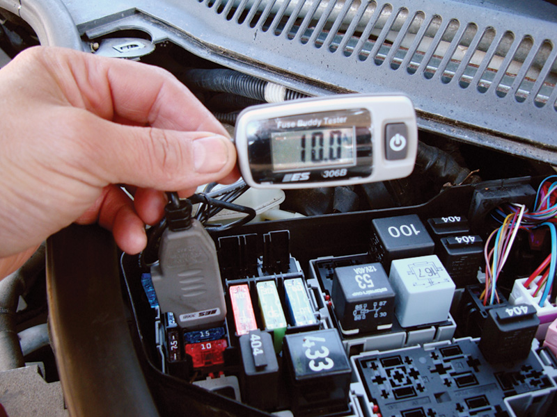
The relay for the transfer pump is mounted in the driver’s side electrical box in position C19 and is referred to in the diagrams as Fuel Pump Relay 2. The relay receives power from the fuse mounted in position S14. With the proper test equipment, you can check the amp draw of each fuel pump without pulling them out of the fuel tank. You can use an in-line amperage tester to monitor the amp draw from the fuses. The main system pump draws about 10A if it is working normally. The transfer pump, when it is activated, will draw about 9A if it is healthy. If the vehicle does not start, you can substitute a jumper instead of either relay and activate the pumps individually. If the engine starts with the jumper in place, the relay is at fault.
Servicing
With the Touareg, in the event that you do find a worn-out or otherwise inoperative main or transfer fuel pump, either can be easily serviced. Volkswagen has provided an inspection plate under the rear seat for each pump. Remove the lower portion of the rear seat to expose them.
In the case of the Touareg, you will also have to remove the mounts for the back portion of the rear seat. These mounting bolts are of the triple-square type, so be sure you have the right socket to remove them. The specific steps for replacing either fuel pump on the Touareg (as well as those for all Volkswagen vehicles) can also be found at erwin.vw.com.
A Safety Note: Before you start any fuel supply system service including fuel pump replacement, remove the fuses and relieve any residual pressure in the system at the tap on the injector rail through your fuel pressure gauge.
To ensure a proper and long-lasting repair, use only fuel pumps provided by your local Volkswagen dealer’s parts department. Aftermarket pump manufacturers often cannot make the distinction between the transfer pump and the main pump, and on models with a saddle-type gas tank with two pumps you do not want to create a problem for yourself during installation. Also, aftermarket pumps can be noisy, and you don’t want the customer coming back with a new complaint.
Consider your Volkswagen parts supplier a partner in your repair business providing you with the correct parts that were engineered to work specifically on the vehicle you are working on. This gives both you and your customer the peace of mind of knowing you’ve installed the right part. Who wouldn’t want that kind of confidence?


0 Comments