
You’ve been dealing with this concept ever since EFI became popular, but now applications are seemingly everywhere.

Relays spanning from the late 1980s to today.
In today’s automotive world, the technological landscape is changing more rapidly than ever before, particularly in the area of electronic controls. Many older technologies are being retired, existing technologies improved and new ones being developed. These shifting technologies bring many new service concerns to the maintenance of proper operation. As an independent service professional (ISP), it’s vital that you keep pace with these changes. Taking the time to learn key aspects of system operation will allow you to develop techniques for making faster and more reliable diagnoses. The ultimate goal is to have a happy customer and perfectly-functioning Mercedes-Benz vehicles leaving your shop.
Analog to digital
The change we want to focus on in this article is electrical switching. Specifically, the gradual move from external cube-type electromechanical relay switching to computer-controlled integrated solid state relay actuation of components. Known as Smart Power, Digital Signaling, or Pulse Width Modulation (PWM) this is now the preferred method for regulating power in a wide verity of applications such as motors, pumps, servos, lamp brightness, and solenoids. Mechanical relays, reliable as they may have been over the years, are still used in quite a few applications, but aren’t up to the task of actuating today’s sophisticated components. Moving from analog circuit control to digital had been fairly slow, but in recent years has picked up speed and become the dominant normal. The demand for greater fuel economy, better performance, energy savings, superior safety systems and creature comforts has been satisfied by digital control. PWM has been an important player in handling the added loads placed on these automotive systems.
Although PWM has been around for decades and is familiar to most technicians as the means of controlling electric fuel injectors, it wasn’t until the development of faster processors and better solid-state relays (semiconductors) with greater load handling capabilities that its full potential could be utilized in automotive applications. Mercedes-Benz has taken versatile PWM technology and engineered its benefits into almost every aspect of electrical operations. You’ve probably noticed that the number of cube relays in the fuse box has dwindled over the years, supplanted by superior integrated computer control.
This advance has been precipitated by the disadvantages of electromechanical controls:
- Bulky
- Rob power
- Noisy
- Generate heat
- Affected by nearby magnetic fields
- Can create voltage spikes when switched off (field collapse inducing high voltage)
- Lack of fine control or “tuneability”
- Subject to wear in moving parts
- Sensitive to environment (humidity, mechanical shock, and vibration)
Meanwhile, the advantages of PWM are many:
- Energy efficient
- Faster switching
- Very accurate control
- Unaffected by vibration
- Cost effective, reliable, & extends component life
- Compact in size — requires less wiring and fewer connections
- Cooler and quieter operation
- Versatile, and can be applied to future innovations

It’s not just for fuel injectors anymore. Here’s the average voltage of PWM signal to the fuel pump on a Mercedes-Benz W204 chassis C350 as seen on a lab scope.
Riding the wave
PWM is the idea of using multiple pulses in succession to deliver a precisely-controlled amount of energy to a motor. This is different from the continuously (linear) applied voltage supplied by mechanical relays, which can only be on or off at a single value, and cannot be switched with any great speed. PWM is achieved through a controller-embedded solid-state relay (semiconductor) that produces digital square waves by switching the power on and off in pulses to regulate the voltage applied to, and the run time of, a specific component. Controlling circuits digitally allows for voltage to be regulated from 0 to 12V, or any value within the set parameters. By pulsating the power on/off (high state/low state) for a varying amount of time known as on-time or duty cycle, voltage can be regulated according to the need. We’ll use a PWM late-model Mercedes-Benz climate control blower/fan speed control as our example. In older vehicles, the regulation of fan speed required the use of variable resistance to control current in the form of a resistor pack, rheostat, or potentiometer to achieve motor rpm slower than full speed. This inefficient method generated lots of heat and wasted power. PWM solves this problem by eliminating the need for external resistors. Using the same 12V, but modulating it in pulses and varying the duty cycle allows the overall average voltage fed to the fan motor to be infinitely variable.
In fixed magnet motors, PWM is essentially “bumping” the armature with voltage. By actuating the motor in this manner, engineers are able to take advantage of the inertia a spinning motor has, taking less energy to keep it moving. A 25% duty cycle would produce an average voltage of 3V. This is enough to spin the motor at low speed. Stepping up the cycle would increase the motor rpm, 50% = 6V, 75% = 9V, and 100% = 12V (full speed). A good analogy for this principle would be spinning the playground merry-go-round we all rode as kids. Once it was moving at the speed we wanted, it only needed to be helped by hand every few revolutions (a lower duty cycle) to keep it in motion. But making it spin faster required pushing every quarter of a revolution (higher duty cycle) to achieve the higher speed.

Electromechanical has been made obsolete. Here’s a vintage relay on a 1970 W113 chassis 280SL. Dependable, but not very precise.
Not only is PWM used to regulate motor voltage, it is also used to actuate solenoids, dim lighting, and transmit data. The versatility of PWM can even be used generate tones of sound.
A peek inside
PWM can be achieved via two means: metal-oxide-semiconductor field-effect transistors, (commonly known as MOSFETs), or solid state relays and a microcontroller. Embedded in the ECU (Electronic Control Unit), the microcontroller is programmed to make calculations based on inputs from switches and sensors. Then, it determines the appropriate output trigger signal sent to the MOSFET, or multiple sets of MOSFETs in higher-amperage circuits. In turn, the MOSFET then flows pulsed voltage to the driven component. Depending on the application, MOSFETs may or may not always be embedded in the ECU. Sometimes they are part of the driven component itself, or a separate dedicated controller. In our example of a climate-control blower/fan, the command signal is sent from the Pushbutton Control Module to the separate Electronic Blower Regulator. From there, the PWM signal is generated and sent to the blower.
More to the story
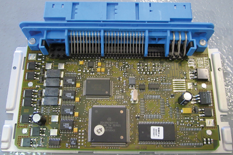
Here’s a modern-day ECU with multiple MOSFET PWM relays.
Frequency, cycles, source, gates, and drains are just a few of the terms used when describing the detailed operations that take place in an ECU. The solid-state components of the systems are not serviceable and are typically not testable in a shop environment. For this reason, we will not go into great detail about actual makeup and specifications of microcontrollers and MOSFETs. But if this interests you, we encourage you to seek out and continue learning about these internal workings. A thorough understanding will serve to make you a better technician by giving greater insight into not only current Mercedes-Benz systems, but into future innovations that will roll through your shop doors one day.
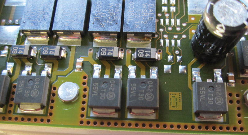
The MOSFETs on a modern ECU board.
PWM is everywhere
We’ve talked about PWM in a climate control blower, but its use in Mercedes-Benz vehicles goes way beyond that. Daimler engineers have applied PWM technology to almost every system in their modern automobiles. Some you may know — and some may surprise you.

The live data stream for a W204 chassis C350fuel pump at idle.
A partial list:
- Fuel Injector actuation
- Fuel pump operation in returnless systems
- Throttle actuator and accelerator pedal
- Exhaust gas recirculation and evaporative emissions solenoids
- Engine cooling fans and electric water pumps
- Transmission shift and torque converter solenoids
- Anti-lock brake and traction control systems
- Electrically-powered steering
- HVAC blend air servos and compressor control
- Dash display, illumination, and tone reminders
- Sound system amplifiers
- Exterior lighting (LED actuation and dimming) and dimmable interior lighting.
PWM Diagnostics
When diagnosing a PWM system, it’s imperative that you know it is in fact a PWM system. The most common tech call we receive is from an ISP unfamiliar with PWM control, and usually only after the damage is already done. Knowing that situations vary, let’s look at some basic steps to help with a successful diagnosis:
- Don’t assume! Check the basics first. You know this, but it’s likely that you don’t always do it.
- Ask: Is it an operator error?
- If there are multiple systems down, what do they share in common? Did you look at a function or wiring diagram? Fuses?
- Are the ground connections okay? As more composite materials replace metals in vehicle manufacturing, the need for good grounding is paramount.
- Checking for error codes with Mercedes-Benz Star Diagnosis or equivalent scan tool.
- Has the vehicle been in a recent accident, had service, been repaired by another service shop, or visited a body shop?
- Are there signs of water intrusion, or corroded connectors?
When it comes down to testing, the DMM (Digital Multi-Meter) cannot be your only tool. Those days have passed and you need to step up and invest in a quality oscilloscope (if you have not already), such as the Mercedes-Benz Hermann Scope or equivalent with data storing capability. Although the DMM is far from obsolete, it does not have a fast enough sampling rate to keep up with today’s PWM signaling.
When it goes wrong
A common mistake when testing a PWM circuit such as for a fuel pump or A/C compressor is checking for voltage at the component with a DMM and not seeing any, or less than full, voltage. Not knowing it’s a PWM circuit could lead you to believe that there’s a lack of voltage supply, or a voltage drop, and in turn you may be looking for a problem that does not exist. Next is making the fatal mistake of applying external voltage to the circuit to see if the component will run. PWM circuits and their components are not designed to run with unregulated “hot-wired” voltage, and doing so will in almost every scenario kill the ECU. This is where knowing the system and using a scope would have been your friends. Being able to see a live pattern could avert misdiagnosis and costly mistakes.
Adding to the physical, digital, and mental toolboxes
For years, the electronics industry has had function generators. These are bench-top boxes capable of duplicating PWM signals for testing purposes. Recently, new tools have hit the marketplace. These new PWM testers, such as CLT1 or PMW Power Pro, have been adapted for automotive use. Portable and easy to adjust, these tools allow for (independent of the microcontroller) a safe way to actuate PWM motors, essentially becoming an ECU simulator.
In life, experience counts for a lot, and if you’re like us the bulk of understanding comes from physically seeing systems at work. This brings to light the importance of not only having the right tools, but also knowing how to use them. With so many different digital signals being generated now, knowing the good from bad can be difficult. Building a digital library will become a priceless tool to the ISP shop, now and in the future. Taking a little bit of time to record known good patterns and the occasional bad signal in various systems that come through your shop will pay dividends in faster, more accurate diagnosis.
Remember, when diagnosing a problem PWM circuit it’s more than just the pulse wave. The complete picture needs to be taken into account. Upstream input sensor data and downstream output actuator data are essential to system function.


0 Comments