

BMW’s new-generation energy management systems are complex, but you can understand them “one bite at a time”…
So, here you are reading an article about BMW energy management. You have to admit that this is not a very sexy subject. But the topic is intriguing enough that you are taking the time to find out what this is all about. In this article you’ll find a comprehensive overview of BMW energy management strategy, the components involved, how to use that information in service, and some service best practices.
BMW’s first bona fide attempt at energy management started with the E65 seven series. How successful that was is debatable but it was a good first start. The E65 seven series, with its increased number of control modules, bus systems and features, launched the era of the modern BMW as we know it now.
BMW added a dedicated power module and software to control the flow of energy in and out of the battery and reduce consumer load when the vehicle was not in use. This increased the likelihood that the battery could restart the vehicle. The original goal was to make sure that the technological wonder known as the BMW E65 would not leave the owner stranded in the country club parking lot and ensure trouble-free operation when driven.
Thankfully for everyone involved, that strategy evolved into the powerful and fantastic system used today. Starting with the launch of the 2004 E6X five series, the energy diagnosis test module added powerful diagnostics for the energy management system. The energy diagnosis test module assists service technicians in determining a cause or causes of a discharged battery.
Those causes may be a bad battery, a closed circuit current draw in excess of 80mA, or excessive vehicle wake ups due to unauthorized bus activity. It could also be a function of control modules that prevent the vehicle from entering sleep mode, i.e. sleep mode preventers, prolonged parking periods, vehicle lighting being left on, ignition being left on or an unfavorable driving profile such as short trips.
With the 09/06 model update of the E6X, the energy diagnosis test module really started delivering detailed diagnostics. As for the E65, the energy diagnosis test module offered very little assistance in determining the root cause of battery discharge. It never reached its full diagnostic potential even after the 05 model update. So our overview of energy management with regard to the energy diagnosis test module will largely exclude this model.
In all Boardnet 2000 vehicles (almost all E series vehicles with a MOST bus), with the exception of the E65 seven series, and all Boardnet 2020 vehicles (F series), the energy management software is located in the DME. That software is responsible for many functions such as: determining the battery condition, determining the required charging voltage, boosting idle speed, requesting power shutdown of terminals and electric loads, and enabling battery discharge.

Let’s take a look at the first item — determining the battery condition. The DME is responsible for the majority of the calculations of the battery condition. It gathers the relevant data from a small sensor/control unit called the Intelligent Battery Sensor (IBS). Using the data from the IBS, the DME is able to increase or decrease the output from the alternator, increase the idle speed to assist with alternator output if needed, and request reduction or termination of nonessential loads if the demands on the electrical system are too great.
The IBS is a Mechatronic component attached to the battery negative lead. It is mounted to the battery negative terminal and has power supply from a fused connection to the B+ terminal of the battery. It has the function of measuring battery voltage in, battery voltage out, current in, current out, and battery temperature under all operating conditions.
The IBS performs minor calculations and forwards its data directly to the DME. The IBS determines the state of charge (SOC) of the battery and is a critical component in determining the battery state of health (SOH). SOC is pretty self-explanatory, it’s the open circuit voltage value or the amount of energy left in the battery. It has some diagnostic value but doesn’t indicate the battery’s ability to deliver current. That is where SOH comes in.
SOH measures the battery’s ability to deliver a specified amount of current when requested. The DME calculates the battery SOH based on the voltage drop across the battery, measured by the IBS, during engine starting. The IBS delivers the state of charge, the value of the current demand from the starter, and the voltage drop across the battery, to the DME. The software in the DME processes those values to determine the battery’s impedance (“effective resistance”) and conductance and derives the SOH value. This process should be familiar to anyone who has performed a load test on a battery with a VAT40.
The DME uses the SOH factor to set the start capability limit and after-start recovery charge strategy. There are other factors used to determine the charge strategy like ambient temperature and battery type and size, which can be covered in charging system basics.
For now, let’s just focus on energy management as it pertains to the energy diagnosis test plan. The start capability limit is the minimum voltage required to re-start the vehicle based on the state of health of the battery. There are typically two start capability limits, an upper and lower, or start capability limit one and start capability limit two. These limits are transmitted to the IBS from the DME prior to the DME entering sleep mode. The IBS will monitor the battery voltage level and wake the DME if the limit has been reached.
Now that we understand how the start capability limit is calculated, let’s look at some of the other terms used in the energy diagnosis test plan.
Before we go much further we must understand the terms used to designate terminal status. By now, you probably have a pretty firm grasp on the basic terminal designations 30, 31, and 15 specified by the standard DIN 72552. Terminal 30 is a line from the battery positive terminal direct. Terminal 31 is a return wire from the battery negative or ground direct. And terminal 15 is switched positive after the battery ignition switch output.
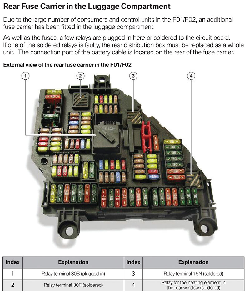
Let’s look at some variations used in energy management. Terminal 30g, also known as 30B in
F series vehicles, is a time-controlled terminal shutdown. This means that control modules and components that are supplied by terminal 30g receive power when the vehicle is on, and remain powered for a specified amount of time after the vehicle is shut off.
The Car Access System (CAS) is responsible for switching terminal 30g on and off using the 30g relay/30B relays. The CAS will open the 30g/30B relays after a specified period of time, from ignition switch terminal 0. In service the general rule of thumb is the terminal 30g/30B relays will be opened by the CAS one hour after ignition off. This time can be shorter if the vehicle does not have a TCU or combox or if it is an F series that has been double locked.
When the CAS opens the 30g/30B relays, that marks the start of “Sleep Mode” and the IBS starts measuring closed circuit current. This means that any control modules or components connected to these relays are disconnected from power after the vehicle enters sleep mode and cannot cause a closed circuit current draw.
Okay, let’s put it all together with an example from an energy diagnosis test plan. Let’s say you perform an energy diagnosis test plan and the results indicate that the most likely cause of the battery fault is: 30g/30B relay. What does that mean? Is there a problem with the 30g/30B relays? Not necessarily.
The reference to the 30g/30B relays is more of an information flag indicating that the relays were switched off before the normal sleep mode switch off time. And since closed circuit current monitoring does not occur until the 30g and 30B relays are shut off, there would be no reason to go looking for a draw.
Instead, the focus should be on looking for what would be causing the battery voltage to drop off. In this case the most likely cause of the fault would be a weak/faulty battery. This strategy is refined and included in battery diagnosis in the energy diagnosis test plan starting with the F10 five series. Typically, a faulty battery that generated the results of the the 30g/30B relay would also generate the information flag: 30g_f/30F relay.
Now we will look at the terminal 30g_f relay also known as the 30F relays in F series vehicles. The 30g_f/30F relays are bistable relays, which means that they are relays that only require power to switch positions and the activation coil does not require power to keep them in the activated position.
The designation 30 indicates the connection to battery positive and the g specifies that it is switched from a relay, followed by the f which stands for fault. So, the 30g_f/30F relays are shut down in the event of faults. These relays are normally on and are only switched off in the event of a fault such as unauthorized bus wake up, the start capability limit being reached, closed circuit current violation, or if sleep mode preventers are identified by the vehicle gateway (SGM, KGM, JBE, ZGM, FEM or BDC).
The 30g_f/30F relay shutdown process starts with a 10 second reset. After the reset, the IBS and/or vehicle gateway will continue to monitor for continued activity. If the condition that caused the reset continues, the 30g_f/30F relays will be opened until the next authorized vehicle wake up and a fault/information flag will be stored.
On the subject of vehicle wake ups, there are a couple things that you should know. One is the difference between an authorized and unauthorized wake up. And another is determining which modules are authorized to wake up the vehicle.
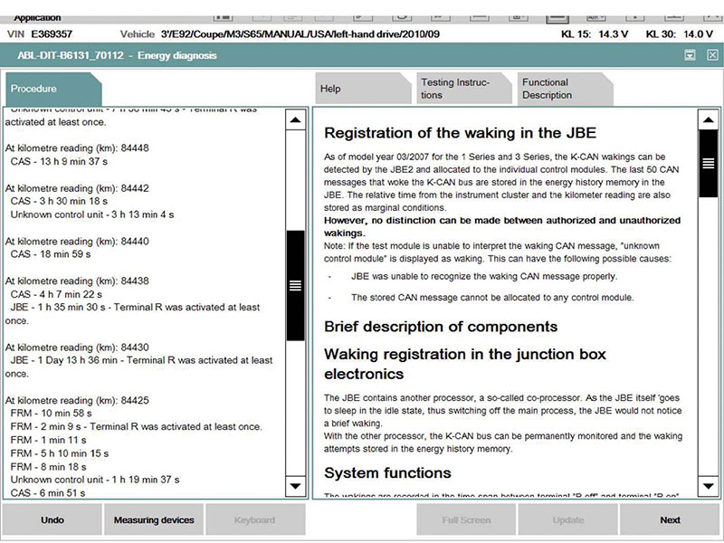
All control modules that wake up the vehicle are logged by the vehicle gateway. This function reliably started with the 9/06 model update for E6X, and continued with more fidelity on all models that were capable of an energy diagnosis test module.
With regard to authorized vehicle wake ups, only two modules are authorized to wake up the vehicle, the CAS and the vehicle gateway, whatever that may be (SGM, KGM, JBE, ZGM). For Boardnet 2020 vehicles using FPM or BDC, those would be the only authorized wake up modules. All other modules that wake of the vehicle are considered unauthorized wake ups.
So, when examining a list of control modules that have awakened the vehicle, the CAS and vehicle gateway can be excluded as unauthorized wake ups, unless their wake-up cycle is abnormal, such as every minute or five minutes etc. Just a note, the KOMBI will show up in the wake up list intermittently throughout sleep mode. This is normal activity and can generally be disregarded.
The KOMBI periodically wakes up to check the ambient temperature as a function to optimize cold start emissions and energy management calculations. When analyzing unauthorized wake up, focus on the modules that are waking up at regular intervals. If there are multiple modules waking up the vehicle, try to determine if there is a common denominator — i.e., common power/common ground switch contacting the sensory input etc. If the focus is on a single control module, all of that control module’s inputs need to be ruled out as the root cause prior to replacing the control module. These can include power and ground, corrosion-free connections, and wiring harness integrity
What is a sleep mode preventer? A sleep mode preventer is the control module that fails to enter sleep mode or set the ready to assume sleep mode bit more than one time after the ignition is switched off (terminal 0). After terminal 0, control modules for relevant data are required to restart and log off of their respective bus systems. The vehicle gateway monitors bus activity and logs which control modules have signed off and assume sleep mode.
Any control module that indicates it is ready to assume sleep mode more than one time is automatically classified as a sleep mode preventer. The majority of the control modules in the vehicle should assume sleep mode in the first 16 minutes (8 minutes for Boardnet 2020 vehicles) after terminal 0. This time frame, 16 or 8 minutes, is considered the first phase of sleep mode, and added conclusion nonessential consumer cut out occurs. That means any interior lights, map lights, convenience lighting and convenience features are turned off.
The vehicle gateway compares a registry of control modules that logged on to the bus during the last vehicle wake up to the list of modules that have logged off and entered sleep mode. The vehicle gateway module checks the vehicle bus system for modules that are communicating/still awake at 5, 10, 15 and 20 minutes after terminal 0. Any module that is still logged on at the 20 minute interval is designated a sleep mode preventer since it should have logged off by the 16 minute time frame.
That strategy is shortened up a little bit for the Boardnet 2020 vehicles since it uses an 8 minute first phase of sleep mode. But you get the general strategy, and now have an understanding of what a sleep mode preventer is. When a control module is identified as the sleep mode preventer, the inputs to the control module need to be investigated and ruled out as possible causes that may keep the module awake prior to replacing that control module. These can include power/ground corrosion-free connection switch contacts that may be monitoring the status of subsystems they may control.
Okay, now for everyone’s favorite subject, closed circuit current draw/violations. As the sophistication of the energy management system progresses with new models, the subject becomes less and less challenging. With the addition of the 30g/30B relays and 30g_f/30F relays, there are fewer control modules connected directly to terminal 30, which means there are fewer control modules that can be identified as causes for a closed circuit current drain.


0 Comments