

When a vehicle presents itself with a crank but no start condition, a few items must first be determined, one of which is, “Does it have fuel?” While this might seem like a simple question of whether or not the gas tank is empty, what we really need to know is whether or not there is adequate fuel delivery to the engine. This question can be answered with a standard fuel pressure and volume test. If the answer is no, it’s time to figure out why.
Checking the flow
First, let’s talk about that initial fuel pressure and volume test. Modern port injected engines have a test port with a Schraeder fitting to allow for convenient measurement. On most BMWs this is located on the fuel rail. However, some models have the test port built into the fuel filter and pressure regulator assembly.
Pressure specifications vary, so be sure to look them up. For a while all BMWs had a standard spec of 50 psi. Over the last decade that has changed. We now see pressures up to 87 psi, and some vehicles call for a variable pressure. As far as volume goes, a good rule of thumb is to look for fuel delivery of a quart in 30 seconds.
No or low pressure or volume can be caused by an empty tank, bad pump, faulty pump control circuit, or a leak in the system. While a lack of fuel delivery will certainly cause a no start condition, low or inadequate delivery may still allow the engine to run. In this latter scenario, the complaint may be a lack of power or misfires, with or without a Check Engine light. In all cases a complete vehicle scan should always be performed. Fuel trim faults indicating a lean mixture in both the “Additive” and “Multiplicative” ranges may indicate a failure to deliver enough fuel volume. Newer vehicles may also have a fuel pump plausibility fault.
The logical starting point
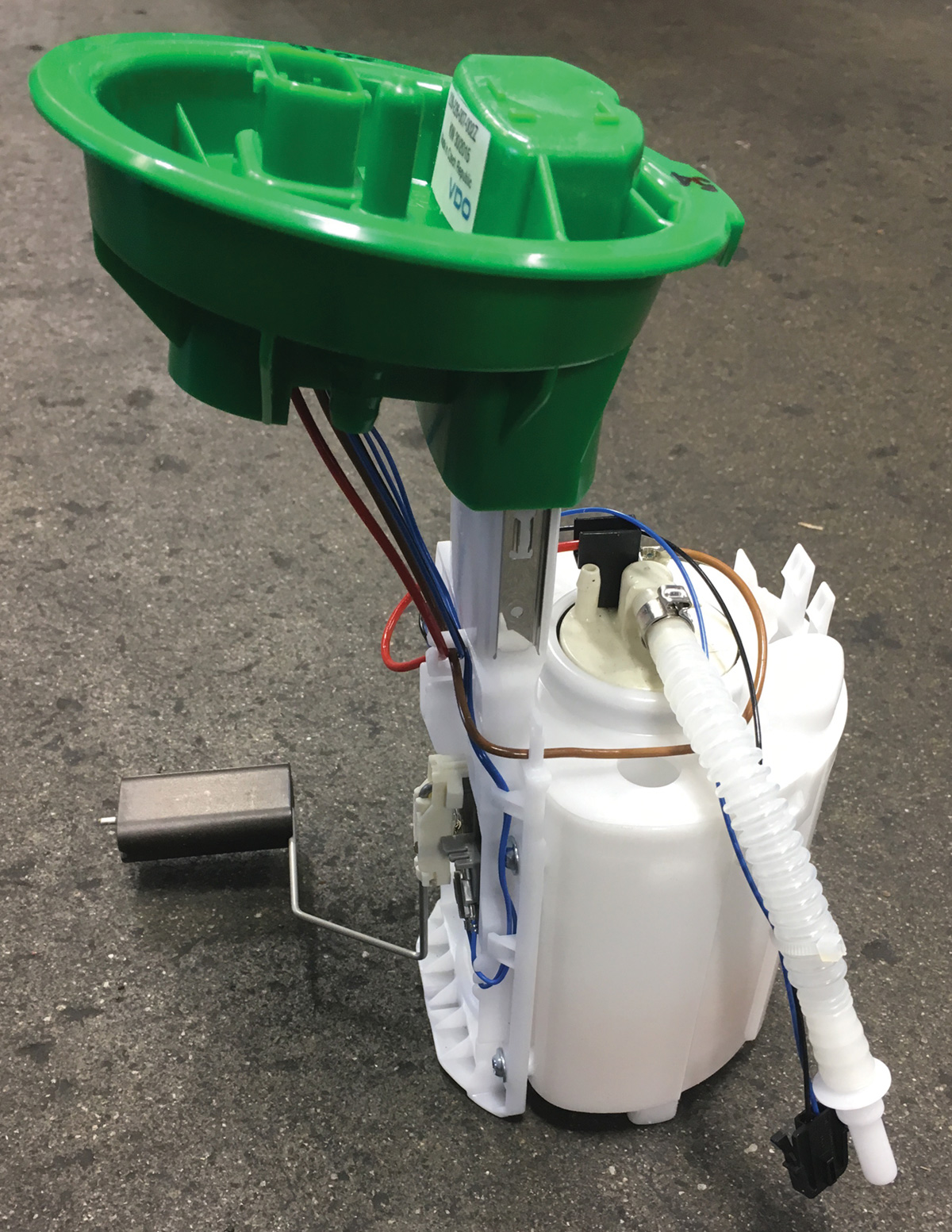
Fuel delivery starts at the tank, so let’s look there first. BMW uses what is referred to as a “saddle tank.” This refers to the shape of the tank. In order to achieve optimal weight distribution, the fuel tank is located beneath the rear seat. To allow room for the exhaust and drivetrain, the tank is shaped like a saddle. This results in two storage areas with a common connection on top.
There is only one fuel pump, located on the right side, so fuel must be transferred from the left side of the tank in order to feed the pump. These design elements are where we can encounter the first possible issues when dealing with no fuel delivery.
Is there gas in the tank? Because of the design, there are two fuel level senders, one on each side. Depending on the model you’re servicing, these provide direct inputs to the instrument cluster, JBE or FEM. The control module evaluates both signals to determine the total fuel level to display to the operator. Obviously a problem with one or both sensors can result in a false display. Another problem can be the failure to transfer fuel from the left side of the tank to the right side. In both of these scenarios, the vehicle will effectively run out of gas even though the gauge does not show empty.
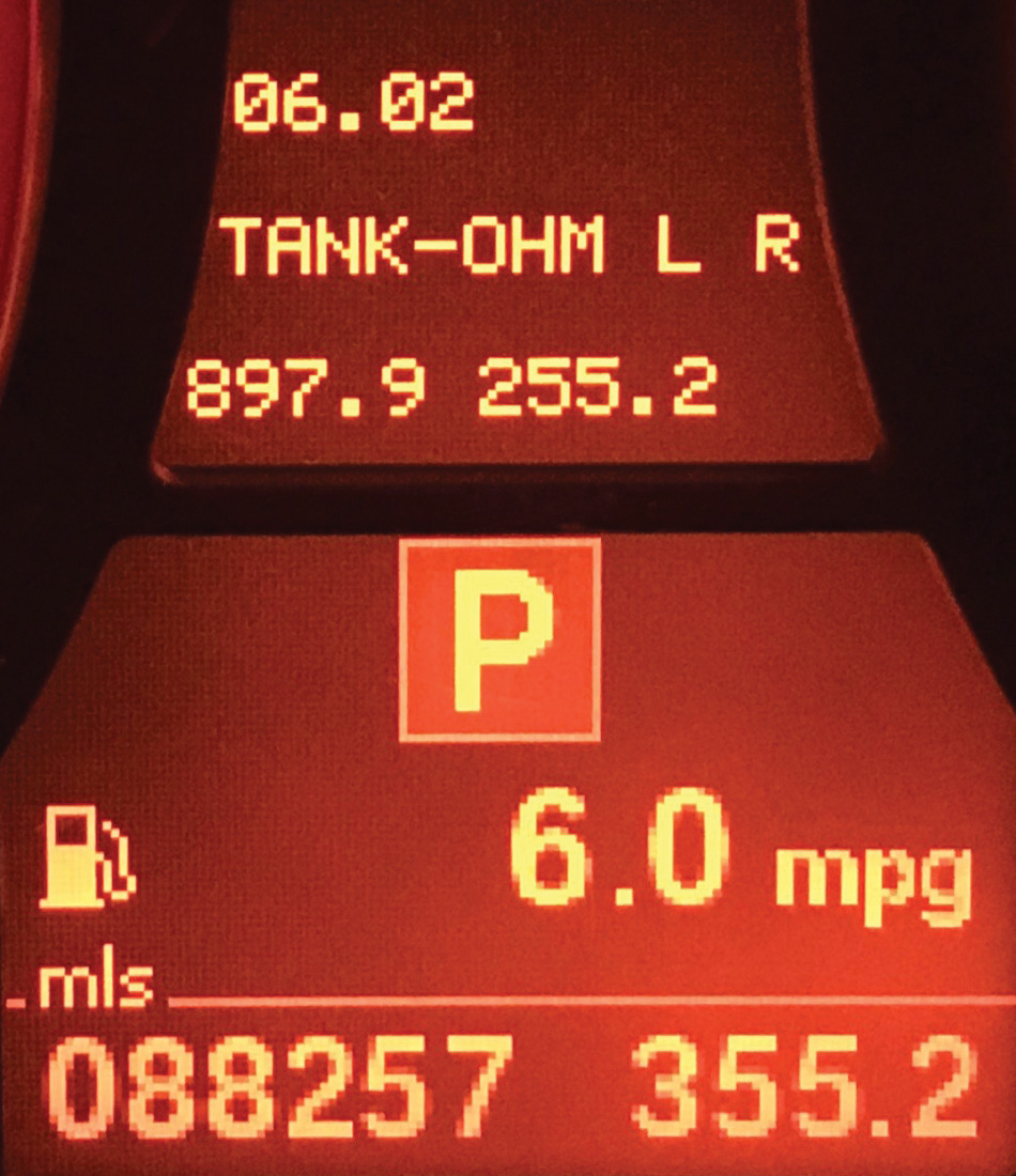
Using an enhanced scan tool, with the ability to communicate with the instrument cluster, you can view live data from both fuel level sensors. You can also go into “Instrument Cluster Test Mode” and call up fuel level data directly out of the vehicle without a scan tool via test number 6. Test 6 may also display the raw data, or actual resistance, of each sender unit. This is displayed in ohms.
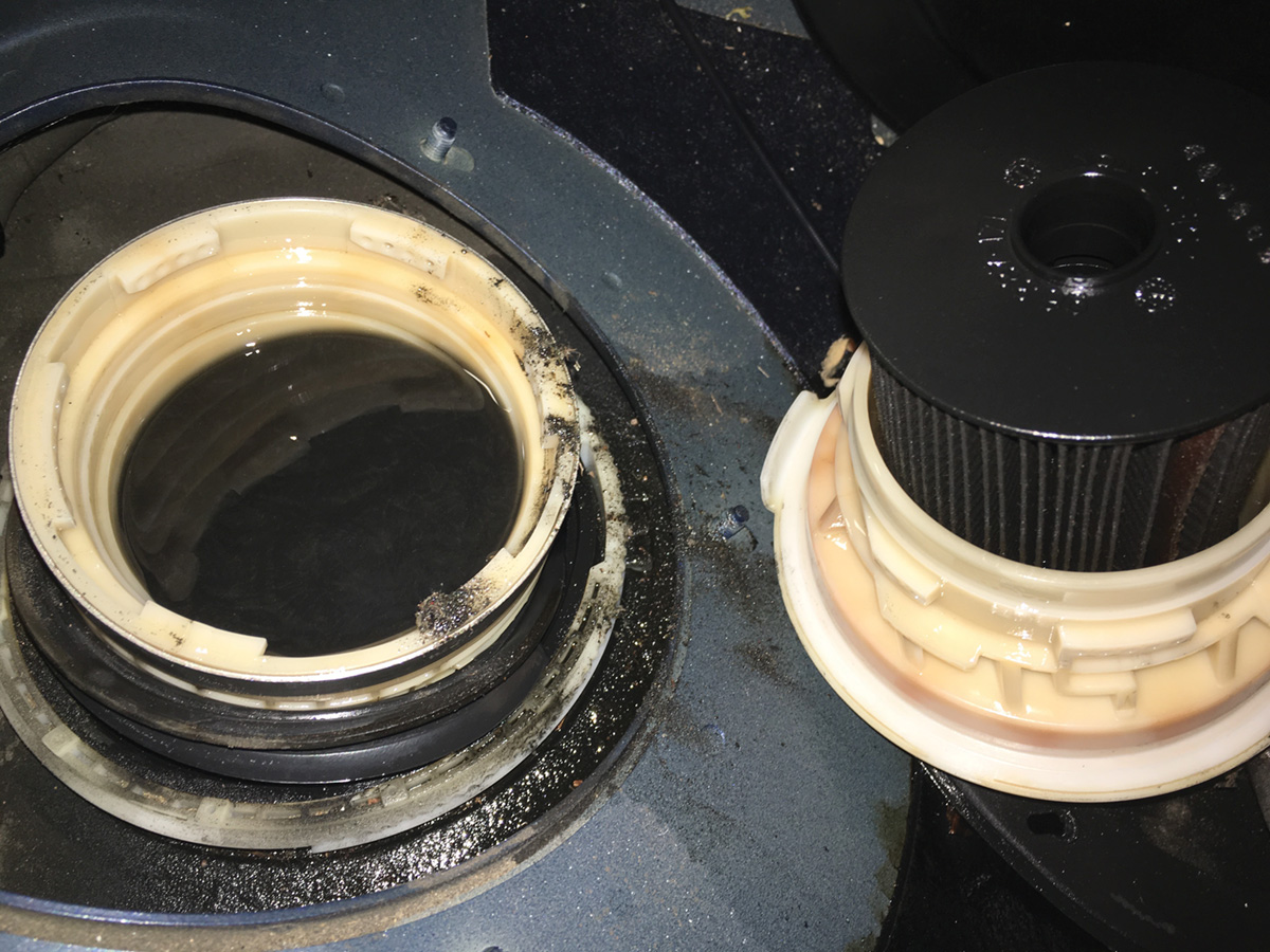
The first thing to note is the comparison of the fuel level in both sides of the tank. There should never be more fuel on the left side than the right side. If so, there may be a transfer problem or a failure with a level sensor. Due to the possibility of a sensor problem, actual fuel level should be confirmed visually. Removal of the access covers for both sides of the tank is relatively straightforward on most models, with the notable exception of “Z” chassis.
Make sure sensors are telling the truth
If, after visual inspection, it is determined that the level readings are incorrect, continue with electrical diagnosis of the level sensor circuit. Sensors are potentiometers, so a voltage drop test while moving the float arm is the easiest test.
When the replacement of a fuel lever sender is needed, either as a result of failure or as part of a replacement fuel pump assembly, there is an important step that is often overlooked. Because this is an analog signal being generated by a mechanical component, wear results in signal degradation. This problem is addressed using adaptation values stored in the instrument cluster or appropriate processing control module.
Now if the sensor was bad, the software has been applying a lot of inaccurate adaptations to that signal. As a result, when the sensor is replaced, the signal will be modified to a point that it too is inaccurate. This can, and often times does, lead to the same symptom the vehicle first presented itself with until adaptations shift back to zero, which can take several full tank refills.
To avoid this problem and a dissatisfied customer, these adaptation values must be reset. This resetting is accomplished via test number 21 in the instrument cluster test mode. Remember, the cluster must first be unlocked. When asked to enter the unlock code, simply add the last five digits of the VIN together. For more information on cluster test mode, visit the BMWTIS website (bmwtis.com) and read the “Driver Information and Displays” section of the body electric training manuals.
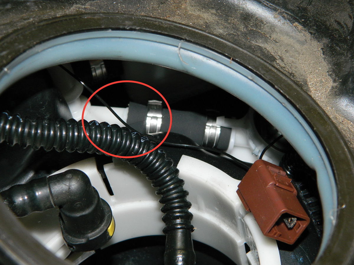
If visual inspection reveals that the left side level is in fact higher than the right side, there is a problem with the siphon jet pump circuit inside the fuel tank. This system relies on return flow and pressure after the fuel pressure regulator. A restriction in the system, like a clogged filter, could result in low flow. A bad fuel pump can also result in insufficient flow.
Another possibility is an internal leak. A hose in this siphon jet circuit can break or come loose at a service connection fitting. While the access covers are still off, activate the in-tank pump. In the case of a broken or disconnected line, there will be fuel spraying out from this leak. A disconnection due to improper installation may be repairable. However, a broken line will likely require the replacement of the entire tank. Some technicians are finding that the plastic corrugated lines used inside of BMW fuel tanks are starting to fail. This is probably a result of the ethanol content in today’s gasoline.
Time to check the circuitry
If initial testing did not reveal any problems with fuel levels, it’s time to check the fuel pump circuit. On early vehicles the pump control circuit is pretty straightforward, consisting of little more than a fuse-protected relay. Now, however, all new BMWs utilize a control module to operate the in-tank pump. At this point we will be doing some electrical circuit diagnosis.
Before starting, be sure the vehicle battery and charging system are in good order. If the vehicle doesn’t start, obviously the charging system can’t be tested. However, the battery may be low on charge due to the several unsuccessful attempts to get it started. Electrical system test results are only accurate with appropriate system voltage. Connecting an auxiliary power supply will assure consistent system voltage throughout the diagnostic process.
To test the fuel pump circuit, you will first need to activate it. Depending on the model and year, this can be done in one of two ways. On earlier BMWs the pump circuit is controlled using a conventional relay. This relay may be located in many different locations, from the engine compartment to the trunk. Once the relay is located, simply jump it via a purpose built tool or a small fused wire with spade connectors on each end. You will need to connect terminal 30 to terminal 87 at the relay socket.
Starting in the early 2000s BMW started varying the fuel pump speed to match load conditions. This first appeared on the E39 and E46 Motorsport vehicles and was later introduced on all chassis. The reason for this was to deliver only the fuel volume needed to meet current load demands plus a little extra to ensure the return system could still transfer fuel via the siphon pump system in the tank. This concept saves energy, reduces wear on the fuel pump, reduces the overall temperature of the electric motor, and therefore helps to prevent unnecessary fuel vaporization in the tank.
All in all this is a great feature. In order to do this, the conventional relay is replaced by an ECU. On those early “M” cars, this ECU was little more than a smart relay. The engine control module, or DME, out puts a Pulse Width Modulated (PWM) square wave pattern to indicate the desired delivery. On these models you can jump the circuit the same way as you would on earlier relay-controlled circuits.
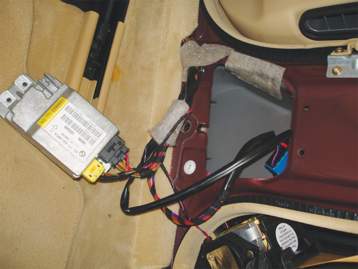
Now all BMWs have a fuel pump control module that is on a bus network. These ECUs are called EKP modules. The first chassis to use this was the E65/66, although on this vehicle it is a unique setup. Instead of a dedicated ECU for fuel pump regulation, the electronics were incorporated into a pre-existing control unit. The module chosen for this task was one of the safety system satellites, specifically the right side B pillar satellite, or SBSR.
The SBSR is on the Byteflight network. This means that the command path for fuel pump control goes from the DME over PT-CAN to the central gateway module, or ZGM. From there the activation signal is sent over Byteflight to the SIM and passed on to the SBSR. Suddenly the importance of a complete vehicle scan becomes clear. On all other BMWs with a dedicated EKP module, the module is on the PT-CAN. So the signal path is much less complicated. As a side note, the EKP module contains one of the two terminating resistors for PT-CAN.
Because the EKP modules are on a vehicle network, they can be accessed via a scan tool. Using your scan tool, live data like pump speed and current draw can be viewed, fault codes can be stored, and the pump can be commanded to run. The speed is controlled via fixed frequency variable duty cycle, also known as PWM.
Your scope is your friend
To ensure accurate circuit analysis, you will have to test using a lab scope. If using a DVOM, the low sample rate will only display an average. For example, 12 volts at a 50 percent duty cycle will be displayed as 6 volts. If you were unaware of this, you would find yourself chasing a power supply problem that doesn’t exist. To avoid this issue, either use a high sample rate digital oscilloscope, or when commanding the pump to run with scanner, select the option of running the pump at 100 percent.
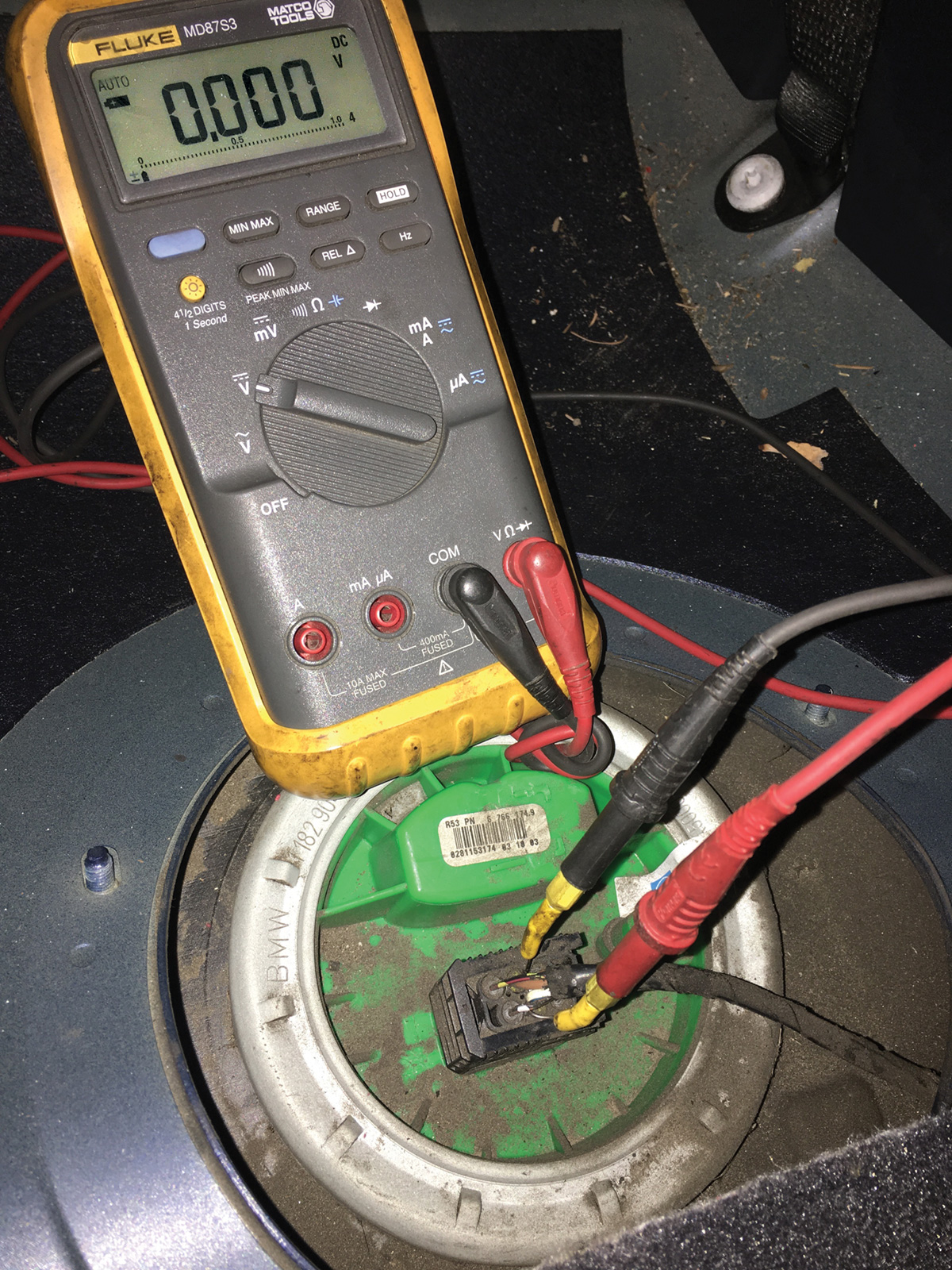
Now that the circuit is complete, or commanded on via scan tool, perform a voltage drop test across the fuel pump connector under the rear seat. You should be measuring within half a volt of system voltage (some will be lost through various connections). If measurement is within spec, and you cannot hear the pump running, clearly the problem is in the tank. Remove the electrical connector and visually confirm that the contacts are not burnt before proceeding with a pump replacement.
However, if the measured voltage is more than half a volt lower than system voltage, there is a problem with the circuit. First determine if the problem is on the power or ground side. This is done by doing a voltage drop test of the complete circuits on either side of pump to the battery. Connect the ground lead of your DVOM to the negative post of the battery, and connect the positive lead to the ground pin on the pump connector. This is a complete ground circuit voltage drop test. A reading of anything over half a volt is a problem.
To check the supply side of the circuit, place the positive lead on the positive post of battery and the negative lead to the power pin of the pump connector. This is a voltage drop test of the entire positive circuit. This test can determine if there are any bad connections or open circuits. Don’t forget, a blown fuse is an open circuit.
Once you have determined which side of the pump control circuit is faulty, it is time to further isolate the issue. Using a wiring diagram, locate all the connections in the circuit. Continue to perform the described drop test at additional locations to divide the circuit. Potential issues can be anything from a burnt connector, loose ground, worn relay contacts, or even cold solder joint failures on the circuit board of the EKP control module. Note that the SBSR is a common failure point with solder joint failures.
Everything discussed here can also be applied to the low pressure side of the fuel supply system in vehicles equipped with direct injection engines. The primary difference is that, in these vehicles, fuel pressure is controlled by EKP regulation using feedback from a fuel pressure sensor located in the fuel line. This is opposed to a mechanical fuel pressure regulator. These systems do not have a pressure test port. Measurements are done via live data stream with your scan tool, or by using an adapter to the tee into the fuel line.
When replacing a faulty fuel pump, you should always replace the fuel filter too. If the repair requires replacement of the EKP module, it will likely need coding or programming. If you are replacing the SBSR, after coding and programming don’t forget to re-start the system time for the passive safety system.
Download PDF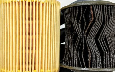

0 Comments