

Continuously Variable Valve Timing makes a biG difference in the efficiency of Volvo engines, but it also complicates service procedures.
Volvo adopted variable valve timing in 1999. The first versions had CVVT (Continuously Variable Valve Timing) only on the exhaust camshaft, but with the advent of stricter emissions regulations and the ongoing quest for better performance, Volvo added this efficiency-enhancing feature to the intake cam. In the ISP (Independent Service Provider) world, most of the Volvos we see have camshaft control, and often require service on that system and the timing belt that powers it.
Early on, technicians were only replacing the belt, the tensioner, and the idler bearing as cars reached the recommended mileage intervals. But more and more Volvos are suffering from a lack of regular maintenance. So problems are developing, such as camshaft seals leaking or popping out, and CVVT valve and unit failure. If a car is on its second timing belt, it’s best to not only replace the timing belt and bearings, but also the CVVT hub or hubs, the camshaft seals, and the water pump. By the way, whenever you find a camshaft seal problem, make sure you check for pressure in the crankcase caused by a clogged PCV system (see Crankcase Breathers are Critical! elsewhere in this issue).
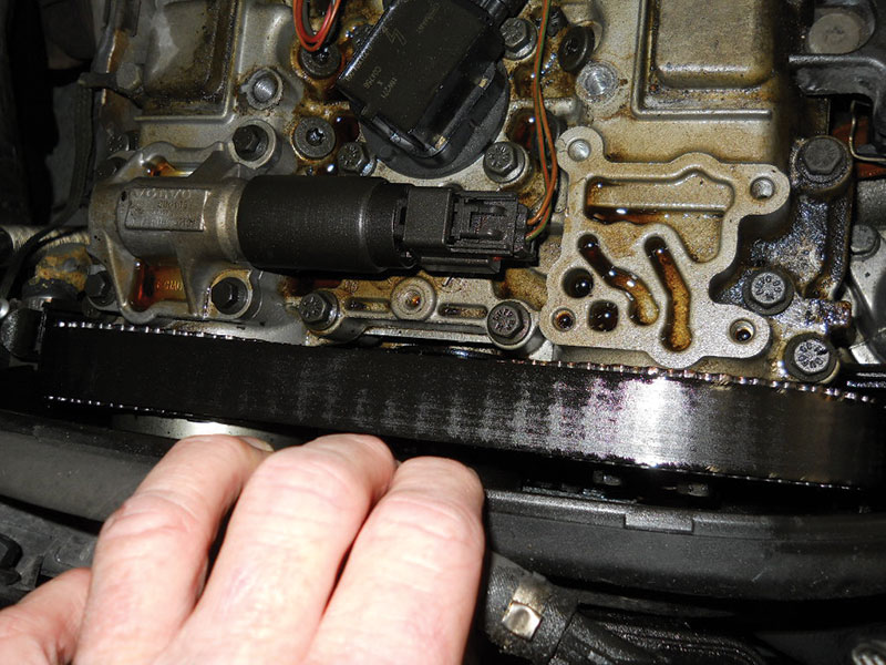
Sometimes a car comes in that’s had no maintenance beyond the occasional oil change at the local “Iffy” lube. You know, “when the oil light comes on.” You’re probably familiar with the condition of the cars they own: lots of dents and scratches, an “interesting” smell inside, as well as most of the newspapers from the last 15 years in the back seat. The customer comes in and tells the service writer that he or she has an oil leak, followed by the statement, “I’ve never had to do anything to this car.” As you drive it onto the rack, you notice that you can’t see out of the back window because it’s covered with oil residue. You look at the oil change sticker on the windshield, but it’s so faded you’d have to use a black light to make out the mileage. And you have at least three warning lights glowing — “Check Engine,” “Service Required,” and “Bulb Out,” with the odd SRS or ABS lights mixed in. You open the hood, pull the dipstick, and — surprise, surprise! — no oil present, yet the engine is dripping with that liquid lubricant. You pull off the timing belt cover, which is distorted, to confirm that, yes, the oil has been pouring out of the front camshaft seals. The timing belt is soaked with oil, and when you test the breather system it shows positive pressure, instead of vacuum.
This is a worst-case scenario, of course. But more high-mileage Volvos are turning up with these issues. As for a car that needs all the work done to correct the conditions listed above, there is only one way to do it: the right way. This customer is going to have to decide to “fish or cut bait” because to do what’s necessary to get this Volvo back from the grave will be expensive. Customers who love their Volvos will have them fixed, whatever it takes. On the other hand, if they ask you to put a band-aid on it, do yourself a favor and don’t. You will thank yourself later when the timing belt jumps off or the engine locks up.
Prelims
Here, we will walk you through one of the most common Volvo CVVT timing belt and seal jobs using a 2003 Volvo XC70 with a 2.5L turbo engine (B5254T2) as our example. As always with a big job like this, test drive the car first and make note of any irregularities. Since the camshaft seals are leaking, test the breather system for pressure first — there should be a vacuum at idle if the PCV system is working correctly. Let’s assume that this car passes the test.
It’s a good idea to read and note the live data from your scan tool, especially those for the cam angle. Of course, you don’t have to do this every time, but it will help you get a sense of what normal readings are and you’ll see what numbers change after the repairs are done.
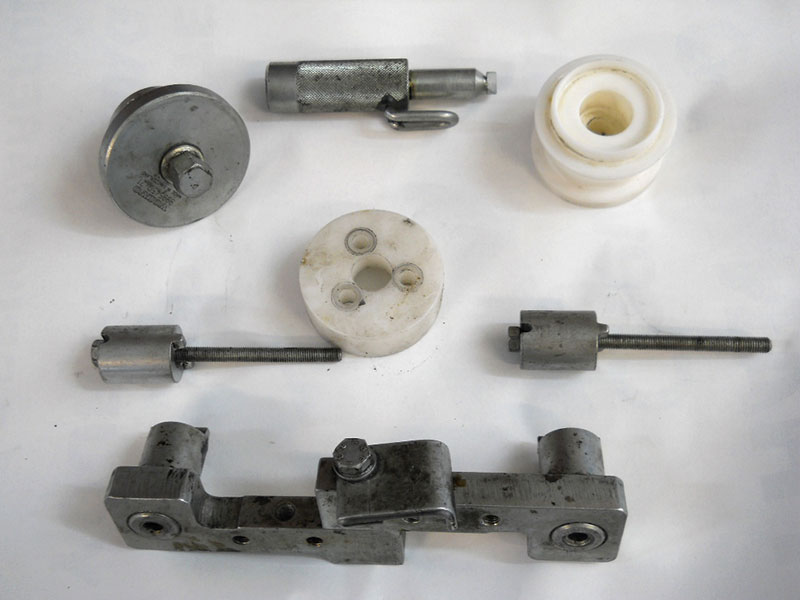
You’re going to need some special tools for this job, which you can purchase at the parts counter of your local Volvo dealer, or online from volvodealersolutions.com. Of course, you can substitute generics for some of them, such as the seal drivers, but the 999 5452 and the 999 5451 are “must-haves.” Here’s a list:
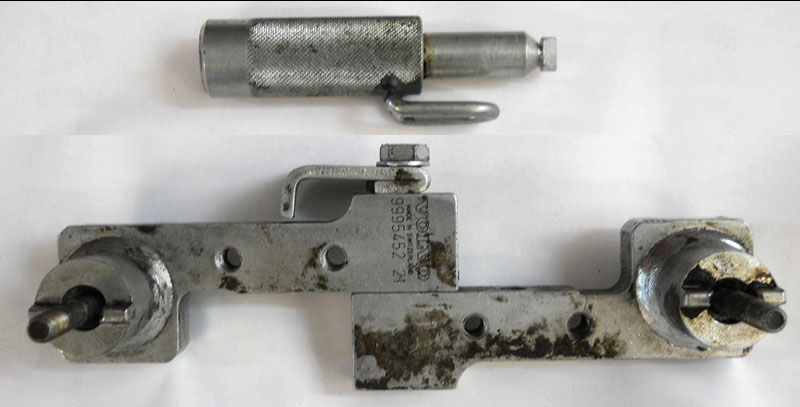
- 999 5452 Camshaft Adjustment Tool
- 999 5451 Adjustment Tool
- 999 5651 Extractor
- 999 5719 Drift
- 999 5718 Drift
- 999 5919 Puller
- 999 5450 Punch
- 999 5433 Crank Holder
Steps
Start the job by removing the negative battery clamp in the trunk. If you’re new to Volvo, you should be aware that you need to wait at least five minutes after the car is turned off to disconnect the battery to let the modules store information. Also, if you disconnect the battery while the climate control is doing its “after-blow,” you can damage the CCM. (This recently happened to a tech — he had to eat a $700 CCM and software, and he was just changing the battery!) In addition, the SRS system is active for three minutes after the key is turned off. All in all, it’s good to be patient.
Open the hood and remove the brace from the strut towers and the upper engine torque member. Take off the intake tube between the air mass sensor and the turbo inlet. Some techs just disconnect the hose from the air mass sensor and pull it to the side to install the cam holder assembly (999 5452 Camshaft Adjustment Tool), but it only takes a few more minutes to remove the tube altogether and it gives you tons more room. The next step is optional — you can remove just the T25 screws for the intercooler pipe that runs over the top of the engine, or remove the whole pipe to gain access to the Torx bolts for the ignition coil cover. Be careful not to pull on the plastic pipe if you’re not going to remove the clamp at the top of the turbo because the short intercooler hose may tear if abused. This can cause a nice unmetered air leak that you may not notice till the customer brings the car back a few days later with a MIL (Malfunction Indicator Lamp) on and a DTC (Diagnostic Trouble Code) for fuel trim.
Unscrew the eight T40 bolts that hold down the upper timing belt cover and coil cover. Next, use soft-jawed hose pliers to pinch off the small coolant return hose going to the coolant reservoir, remove the clamp, and disconnect the hose. If you’re going to replace the water pump as part of the job, drain the coolant before you start. If you’re not, you can leave the coolant in the reservoir — we use a small plug to block the nipple on the reservoir.
Disconnect the coolant level sensor wire at the base of the reservoir and lift the power steering and coolant reservoirs up and out of the way. You may spill some P/S fluid but probably not much. Pull the reservoirs and hoses away from the cam sprockets.
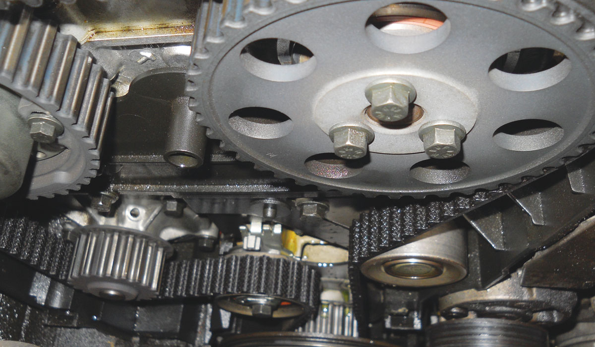
Raise the car, remove the right front tire and the two plastic 10 mm nuts that hold the bottom of the fender liner in place, and hold the bottom edge of the liner out of the way so you can see the crank pulley. Lower the car and remove the serpentine accessory belt. It’s a good idea to draw a map or take a photograph of the belt routing before you remove it, unless you know it by heart. Unscrew the main timing cover bolt and lift the cover up and away. Now you can see all the timing marks.
Install the upper timing belt cover so you can see the timing notches. With a 32 mm socket, turn the crankshaft clockwise until all three marks align, rotate the crankshaft clockwise 1/4 turn past the marks, then back counter-clockwise to the marks. At this point, we use a permanent marker to make our own marks on the camshaft gears and the head (this is the TDC position). After you remove the timing belt, the camshaft or camshafts (with dual CVVT) will be able to move independently.
To take off the timing belt, remove the crank pulley (four 10 mm bolts first, then one 32 mm nut — Volvo recommends the use of holder tool 999 5433).
Loosen the 12 mm bolt on the tensioner and you can turn the eccentric clockwise to let the belt loose. With the belt off, we then turn the CVVT hub by hand to its rest position and make another mark. Marking the camshaft in the TDC and rest positions is a good habit even if you’re just replacing the timing belt by itself because it’s extra insurance that you get the cam timing correct the first time.
Since here we are replacing the CVVT hub and camshaft seals, we need to lock the cams and crank in the TDC position with the special tools (999 5452 and 999 5451). The reason for this is once you remove the CVVT hub there is no accurate way to tell if the camshafts are in the correct positions even if you mark the gears and manage not to move the cams during the job.
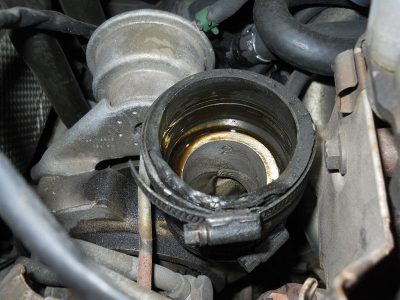
At the back of the head, remove the bolts for the wiring harness bracket and move it away from the head, remove the two 10 mm bolts that hold the cam position sensor on and lay the sensor to the side. Mark the head and trigger wheel with your permanent marker, then unscrew the 10 mm bolt that holds the trigger wheel. It is hard to put the CPK wheel on the wrong way, but we have seen it done. Just get in the habit of marking things and it will save you a lot of headaches. On the intake side there’s a rubber-covered plug. Insert a flat screwdriver into the slot in the center of the plug and pop it out.
Time to lock the cams. Take the cam tool (999 5452) apart and install one side in the slot on the end of the exhaust cam, then install the other side of the tool on the intake side — carefully turn the exhaust cam clockwise with the tool until the two parts line up in the middle. Install and tighten the bolt that holds the tool together. If you did it right, both cams will be locked at TDC. The crankshaft should be lined up with the notch on the block, and you can insure this position by removing the starter and installing the crank holding tool (999 5451). It is best to line up the crankshaft with the timing mark and don’t use the crank lock since it’s easy to see if the crank is in the right position and it usually doesn’t move.
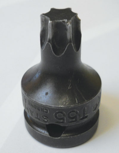
Now take a short T55 bit and remove the threaded plug in the front of the CVVT hub on the exhaust cam. You will need a pretty stubby bit (about 20 mm long) because there’s not much room between the cam and the strut tower.
Next, remove the CVVT hub assembly. With the cam-holding tools tight, you’re supposed to be able to loosen the T55 inside the CVVT hub with just the cam tool (999 5452) holding it, but that bolt gets very tightly stuck in high-mileage cars, and techs have been known to break the tool, or, worse yet, chip the cam at the back. Since you’re replacing the exhaust hub anyway, hold the sprocket with a chain wrench to protect the tool and the camshaft while breaking the CVVT bolt loose.
Once you’ve removed the cam sprockets, the tensioner, and the timing belt idler, use some parts cleaner to get the oil and sludge off the front of the engine. If you’re going to replace the water pump, now is the time. Next, remove the front cam seals and press the new seals into place (the exhaust seal is thinner than the one for the intake). You can replace the front crank seal too, but it’s rare that one would fail on a late-model Volvo.
By the book
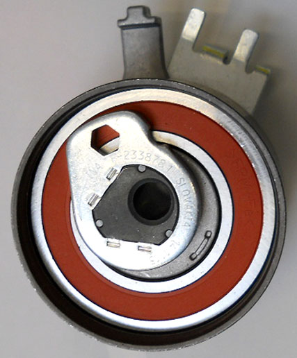
Now comes the fun part: Reassembly. You need to take extra time to make sure you do the installation by the book because if you are off just a little, you will have a comeback and have to do the job over. Install the timing belt idler pulley bearing and torque the bolts to 15 ft. lbs. Put the tensioner assembly on, but leave the bolt loose for now.
Examine the new CVVT hub for defects, make sure the seal on the inside lip is okay, slide it on the end of the exhaust cam, thread the bolt in, and tighten it lightly. You will notice there is no timing mark on the new gear, but don’t worry about the position right now. Make sure the mark on the crank sprocket is still lined up with the notch on the oil pump. Loosen the three screws that hold the sprocket to the CVVT unit, turn the sprocket so that the bolts are centered in the slots, and tighten the three screws slightly.
This next step is critical: Turn the sprocket clockwise to its stop position — you’ll feel it. With the upper timing cover on and holding the gear in its stop position, make a mark on the sprocket that lines up with the notch on the timing cover. If you are reusing the CVVT unit, you can use the old mark — just make sure it lines up with the marks at the full-stop position. At this point, if the mark on the CVVT lines up with the mark on the timing cover when you turn it clockwise with your hand, you can torque the center bolt to 95 ft. lbs.
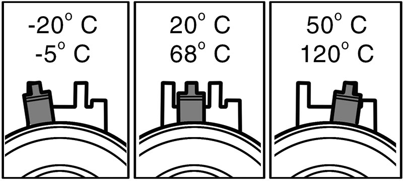
To install the timing belt, start at the crank sprocket and go up to the idler pulley, then to the intake cam, then the exhaust cam, next the water pump, and finally the tensioner. For the fine tuning, hold the center 12 mm bolt on the tensioner and with a 6 mm Allen wrench turn the eccentric clockwise until the indicator passes the marked position and reaches the end position, then turn the eccentric back until it reaches the position in the accompanying diagram. Hold the wrench in place and torque the tensioner bolt to 15 ft. lbs.
Last but not least, to make sure the CVVT hub is at the right position install the center plug on the end of the CVVT hub and torque it to 26 ft. lbs. Loosen the three screws on the CVVT sprocket or sprockets and with a torque wrench and a T55 bit in the cam plug, hold the gear at 19 ft. lbs. and at the same time with a second torque wrench tighten the three outer gear screws to 7.5 ft. lbs. This is to make sure that the CVVT hub is at its end position.
As with all timing belt jobs, turn the crankshaft at least two full rotations and make sure all the marks line up and the tensioner is in the right place. Put everything else back together, fill the cooling system, test drive, and you’re done.
A word about parts: We know it’s tempting to use aftermarket parts because of the savings, but there’s a big difference in quality. With this labor-intensive job, IT’S NOT WORTH THE RISK! So, for the sake of both your customer and your shop’s reputation, use only Volvo OE parts.


0 Comments