
Adaptive cruise control, lane departure warning, blind spot monitoring, cross-traffic alert, park assist — Do you know which Advanced Driver Assist System (ADAS) and comfort technologies are on the vehicle in your bay? Which need calibration, initialization, or resetting, and when? We give you tips on how to address these questions, and why each is important.
When power is removed from an electronically-controlled system due to collision, replacement of a component, disconnecting power to do other repairs, or simply from a low battery charge, some control modules lose the information stored in their memory.
The lost information may include the operating parameters that tell the Electronic Control Unit (ECU) how to control the component, identification codes that verify that the component is appropriate for the vehicle based on its as-built configuration, or even confirmation that the part was legally acquired rather than transferred from a stolen vehicle.
Not Plug & Play
After power is restored, these systems must be initialized or calibrated in order to function properly. This includes the ECU for a component that has been removed or replaced, even if the ECU itself was not removed. Initialization of the ECU is part of the process of re-establishing communication between the two devices.
Initialization may be a simple “handshake” to identify the replaced component to the ECU so that each will recognize and communicate with the other. A more involved initialization might also provide the ECU the operating parameters for the replaced component to. These operating parameters are often enabled on the replacement component when you enter a valid identification or serial number for the part.
Some components are shipped blank. The operating parameters (software) must be copied and saved from the original component, or can be downloaded from the Toyota Technical Information System (TIS) website or authorized third party source.
CRIB Sheet
Safety, driver assist, and comfort/convenience technologies differ by year and model within the Toyota vehicle line. Look up diagnostic and repair procedures in the Toyota repair manual for the specific model on which you are working. Also, check for Technical Service Bulletin (TSB) and Collision Repair Information Bulletin (CRIB) documents related to the model and system or component you suspect needs diagnostic attention.
Many issues with electronically-controlled systems can be addressed with software downloads or online updates, which often are announced via TSBs and CRIBs. To find CRIBs in TIS, go to the Library tab, select “Service Information,” then select the “CR” tab (middle of page) and type “CRIB” in the keyword search box. TIS will show a list of all CRIB documents related to the vehicle year and model you’ve selected.
Before disconnecting the battery or removing the damaged electronically-controlled component or ECU, check the installation procedures to see whether or not you’ll need the serial number or other identifying information for input for its replacement. If so, write down or save in your scan tool any part number or other identifying information about the original component or ECU.
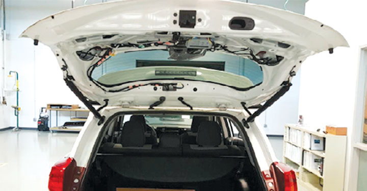
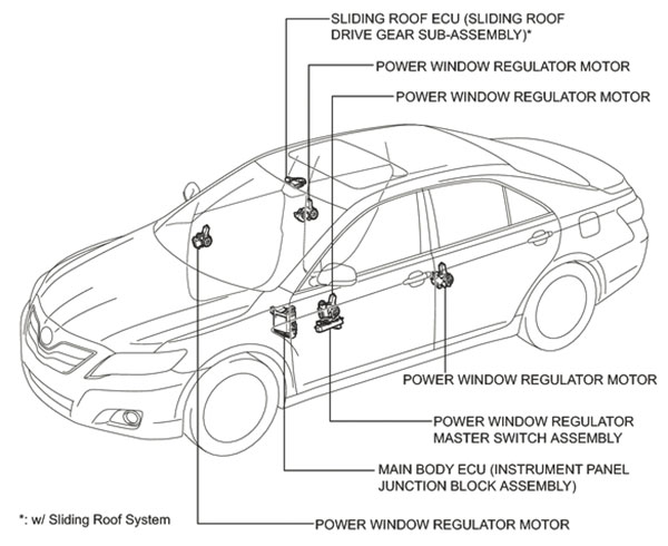
Common examples include the settings for the electric motors that control comfort and convenience features such as power seats, power windows, sliding roof, and back door closers.
Motor Operating Parameters
The information about the normal start and stop positions of a seat, window, sliding roof or door is stored in the ECU or other control module. When power is disconnected, the ECU for many of these systems loses those motor position guidelines, and must re-learn them in order to properly operate the component. Initialization is the process that “teaches” the ECU the start, stop and other measurements relevant to operation of the motor and the moving component.
Motorless Systems
Some systems without motors also need to store component position information. Vehicle won’t start after a steering system repair? If the steering lock ECU was not calibrated after having been disconnected or replaced, that prevents the starting system from working. North, south, east and west directional indications in the driver’s rearview mirror or dash not accurate? The compass may need calibration. Initializing the ECU with component position data in each of these motorless systems is referred to as calibration.
Is the owner’s complaint about problems with Vehicle Stability Control (VSC) or parking guidance systems? One possible cause is failure to calibrate the Steering Angle Sensor (SAS) after an alignment or SAS replacement.
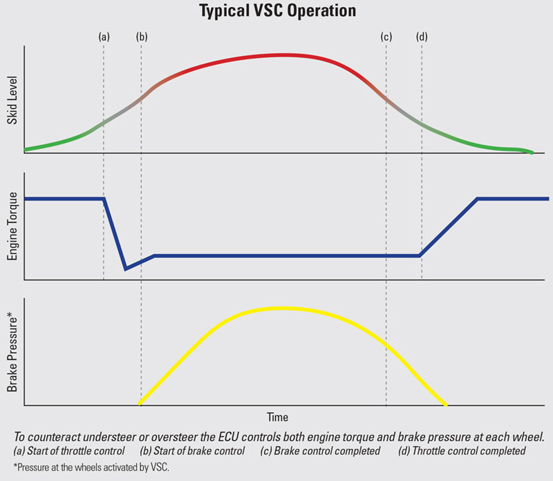
The VSC system uses the SAS along with a combined yaw rate & acceleration (G) sensor to detect when the vehicle’s direction of travel does not match driver steering inputs. The SAS provides information about where the driver wants the vehicle to go (steering wheel input), the yaw rate & deceleration sensor reports where the vehicle is actually going, and the skid control ECU takes action to restore vehicle dynamics when steering intent and actual direction of travel don’t match.
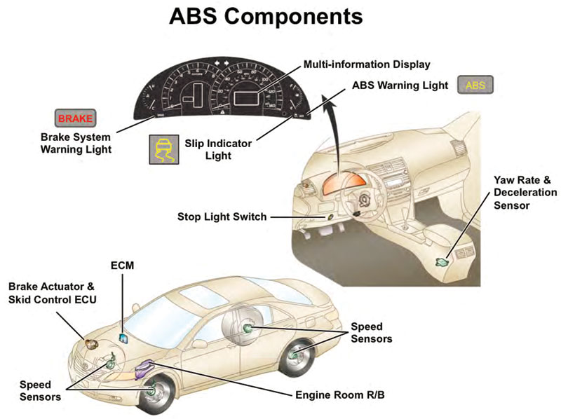
If the SAS or yaw rate & deceleration sensors are providing inaccurate information, the VSC system will malfunction and set a trouble code. The SAS and yaw rate & acceleration sensors must be calibrated after any of the following: replacement of the steering wheel or steering angle sensor, opening the connector hub from the SAS to the steering column, any accident repairs due to damage to the SAS assembly or any part of the steering system, or completion of a wheel alignment. Also, if the Skid Control ECU is replaced or disconnected from power, the yaw rate & deceleration sensor must be calibrated.
Future Vision
Toyota is pushing the envelope with state-of-the-art camera, radar, and laser-based technologies to extend and enhance awareness of the vehicle position relative to objects all around it. Used in various combinations in Toyota’s Dynamic Radar Cruise Control (DRCC), Lane Departure Alert (LDA), Multi-Angle Monitor, Brake Assist, backup/parking assist and other accident avoidance systems, these technologies help Toyota’s safety offerings outrank those of more expensive vehicle makes.
Depending on the model and equipment package, cameras may be attached to the front windshield, embedded in front or rear bumpers, or mounted in the rear deck lid and/or side mirrors. Calibration ensures that the cameras point in the desired direction. They all need calibration after replacement or after any collision repair that involves removal or adjustment of the body part (windshield, bumper, deck lid, etc) on which the camera is mounted. Special calibration targets, tools and procedures may be required. Refer to TIS for the specific calibration procedures for the vehicle in your bay.
Toyota uses radar and laser technologies on selected models to measure distance from objects ahead, behind, and to the sides of the vehicle. This distance information provides input to Toyota’s DRCC (adaptive cruise control), Lane Departure Alert, Brake Assist, Multi-Angle Monitor and other collision avoidance systems. The components need calibration to be pointed in the right direction, and also to recognize the difference between one meter and 100 meters.
Different combinations of technologies are offered on different Toyota models and, depending on the vehicle model, may have different calibration procedure requirements. Most will set trouble codes when there is a fault, but they may not all turn on a MIL. Scan for trouble codes before you begin any repairs. What you find will aid in problem diagnosis, as well as help in developing a repair plan. Scan again after repairs to help ensure that you did not miss anything, including required calibration and initialization procedures.
Check the Toyota Information System for VIN-based confirmation of which Safety Sense systems are on the vehicle in your bay. Access to TIS, including repair manuals, technical bulletins, reference and training materials and other valuable information is available at techinfo.toyota.com for as little as $15.00 for 48 hours.
Communication and Collaboration
Plug and play is an automation of the process of enabling communication and collaboration between devices. Because many different technologies are being applied to accomplish automotive objectives, you may have to take the necessary first steps to enable teamwork between some devices and systems. The payoff is that the vehicle control modules will know which components are installed in a given system, how to communicate with them, and what operating parameters enable the devices to meet factory performance specifications.
0 Comments