Electronic power steering offers many benefits compared with engine-driven mechanical power steering. But diagnostic and repair procedures are very different. Here’s what you need to know.
EPS offers several advantages over hydraulic power steering (HPS). One of the primary drawbacks of HPS is that the hydraulic pump is typically tied to the internal combustion engine (ICE). When ICE rpm is low, the pump rpm is low. When the pump rpm is low, it produces less pressure and consequently cannot provide as much assist. The problem with this is that some of the driving conditions that require the most steering assistance are also conditions where the engine rpm is low, such as when parking the vehicle.
Another problem with steering assist being tied to engine rpm is that a large percentage of Toyotas are hybrid vehicles. Toyota hybrid vehicles drive with the internal combustion engine rpm at zero in many conditions, so an HPS system wouldn’t work at all.
Fuel efficiency is another area where EPS shines. The power steering pump must always generate pressure so that assist is available when the driver needs it. Building pressure requires power, which comes from burning gasoline. Therefore, HPS inherently decreases fuel economy because it generates pressure to provide assist, even when assist is completely unneeded.
EPS has the edge when it comes to reliability as well. As mentioned previously, the hydraulic pump never gets a break and is working whenever the engine is running. Its seals, bearings, and pump elements are all wearing parts. Likewise the seals and bushings on the rack wear, eventually causing fluid leaks. Also, the high pressure hydraulic hose flexes every time the driver accelerates or decelerates, eventually leading to a leak. On the other hand, EPS failures are almost non-existent on most models.
Finally, EPS has the advantage of dovetailing nicely with modern Advanced Driver Assistance Systems (ADAS) as well as future self-driving systems. ADAS features such as Lane Keeping Assist (LKA) and Advanced Parking Guidance System (APGS) require EPS so that the EPS ECU can steer on its own.
Torque Sensors
In order for EPS to help the driver turn the front wheels in the desired direction, the EPS ECU must first know which direction the driver wants to turn. This is where the torque sensor comes in. A torque sensor is built into the steering column or pinion shaft to measure the driver’s input. When the driver turns the wheel to the left, the torque sensor provides input to the EPS ECU so it knows how far the driver is turning the wheel to the left. Obviously, the torque sensor also registers how far the driver turns to the right.
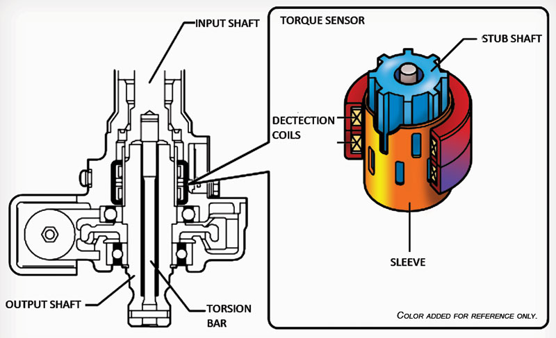
So, how does a torque sensor work? There are three types found in Toyota vehicles, and they all work differently. However, they all have one thing in common, so let’s cover that first. All three torque sensors use a torsion bar. For our purposes, a torsion bar is a thin round rod that twists when torque is applied. The more torque that’s applied, the more it twists. Like a spring, a torsion bar will return to its original state once you stop loading it.
You may have already guessed how the torsion bar is used in the steering column or pinion shaft. The upper portion of the column (steering wheel side) is connected to one side of the torsion bar. The lower portion of the column (rack side) is connected to the other side of the torsion bar. When the driver turns the steering wheel, the torsion bar twists. The torsion bar will twist proportionally to the amount the steering wheel is turned, so the farther the driver turns the wheel, the more the bar will twist and the more the upper half of the shaft will rotate in relation to the lower half of the shaft.
Let’s imagine taking a ruler and drawing a line along the top of the upper and lower halves of the column shaft. The upper line would move to the left of the lower line when we turned the wheel to the left, and vice versa when we turned to the right. Obviously the EPS ECU doesn’t look at a line drawn on the top of the upper and lower column shafts, but it does monitor the relationship between them. Toyota uses three different types of sensors to do this.
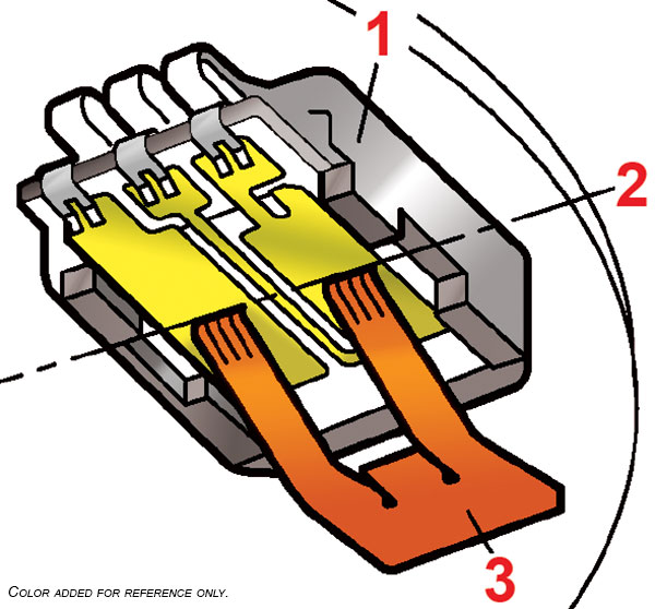
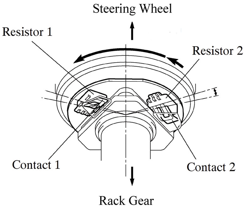
The earliest type was a resistive strip sensor. This type of sensor works by applying a regulated voltage to both ends of a resistive strip, positive on one end and negative on the other. A wiper that moves along the strip generates the sensor’s output. Since the strip’s resistance is linear, the voltage at the point where the wiper contacts the strip will vary proportionally to its position on the strip. The strip is fixed to one side of the torsion bar and the wiper is fixed to the other. When the driver turns the wheel and the torsion bar twists, the wiper moves along the strip and the output voltage varies proportionally to the amount of twist.
Since steering is so important, we need to make sure the output is accurate. Imagine a driver wanting to turn left, but due to a sensor malfunction, the EPS ECU applies “assist” to the right. That wouldn’t be good, right? So, to insure the accuracy of the sensor output, this type of sensor is redundant. Instead of one strip and one wiper, there are two strips and two wipers.
Toyota labels these outputs as VT1 and VT2. At rest (not turning the wheel) VT1 and VT2 will be nearly identical, typically around 2.5 V. When torque is applied, VT1 and VT2 voltage will change in roughly proportional, but opposite, directions. Even though the VT1 and VT2 voltages aren’t the same when torque is applied, they do “agree” because the voltage for both VT1 and VT2 have moved proportionally in opposite directions from their resting voltage. If the sensor outputs ever don’t agree, power assist is halted; it’s much better to have no assist than “assist” in the wrong direction. This type of sensor did occasionally have problems and is no longer used. Two varieties of more robust sensors are still in use.
Modern torque sensors have no moving parts and rarely if ever fail. Both modern types of torque sensors sense changes in the position of ferrous elements attached to the torsion bar. There is never any contact between any part of the sensing device so there is no wear with use or sensitivity to shock or vibration.

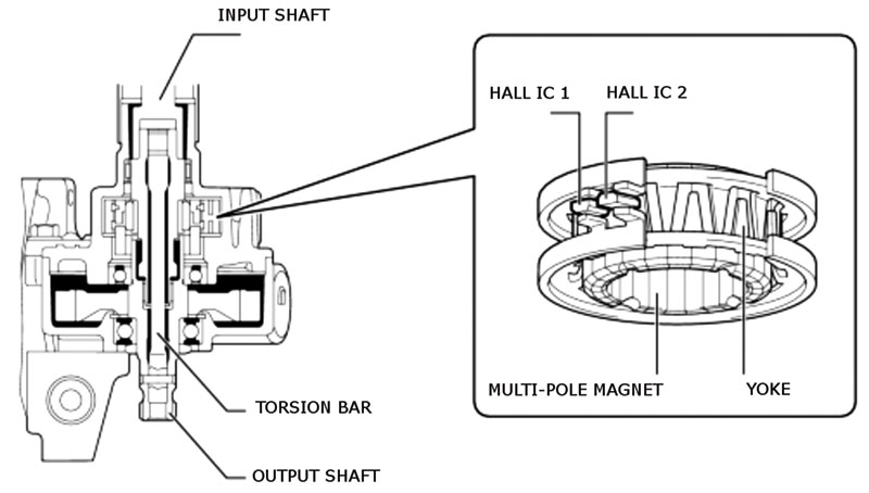
One style of non-contact sensor is the Hall IC style. A Hall Effect IC is a chip that generates a varying voltage depending on its proximity to a magnetic field. Two Hall IC chips are used to detect the changes in magnetic flux caused by the movement of a multi-pole magnet in relation to a ferrous yoke. The multi-pole magnet is attached to the output shaft. The yoke is attached to the input shaft. When the torsion bar twists, the yoke disrupts the magnetic field of the multi-pole magnet and the Hall IC chips sense the change.
It’s a complex sensor, but diagnosis is easy, since we only need worry about four wires: power (TRQV), ground (TRQG), and the outputs: TRQ1 and TRQ2. Power is a regulated 5 V reference provided by the EPS ECU. The sensor ground is also provided by the EPS ECU. The two outputs look just like the old resistive strip style sensors – both are 2.5 V at rest, and then vary in opposite directions proportionally to the amount the steering wheel is turned by the driver.
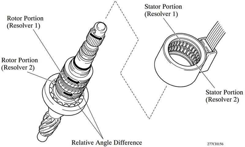
The third type of torque sensor is the resolver type. A resolver is an extremely robust absolute position sensor that is also used to determine rotor position in some EPS motors. Unlike the resistive strip and Hall IC sensors, the input and outputs aren’t easily checked with a DVOM.
Sensor input is a sine wave generated by the EPS ECU. This input is applied to a stationary coil of wire, which creates a magnetic field that oscillates with the AC sine wave. The output is also a sine wave that is generated by another stationary coil of wire. The first coil creates an oscillating magnetic field which induces a voltage in the second coil, creating an output sine wave.
At this point in the description we have a 1:1 transformer, but what are we missing? The iron core, right? Instead of sharing a common core, ferrous elements connected to the steering column shafts transmit the magnetic field and cause the input and output sine waves to lead or lag one another. The difference in the point at which the AC wave passes 0 V indicates the position of the ferrous element and can be used to determine position. By comparing the position of the sensor on the input shaft to that of the sensor on the output shaft, the flex of the torsion bar can be determined.

So how do we test this type of sensor? As always, the Techstream is always the best place to start. Manual measurements as a first line of attack were a dying paradigm at the turn of the century. In addition, many vehicles have an integrated ECU and torque sensor, making direct testing of the sensor impossible and irrelevant. Human readable data is calculated by the EPS ECU based on the raw sensor output. If you check the data list you’ll find the familiar TRQ1 and TRQ2 sitting at 2.5 V when you aren’t turning the wheel. However, if we have a specific code such as C1511 on an older Camry hybrid, using the harness and resistance checks in the manual is probably the fastest way to an accurate diagnosis.
Calibration
Regardless of which type of torque sensor a vehicle has, it must be calibrated when either the sensor or the EPS ECU is replaced. Due to manufacturing variances, each torque sensor is a little different. A calibration is performed at the factory so the EPS ECU knows what to expect from the sensor. If the sensor is replaced, the old calibration must be cleared using the reset memory utility in the EPS ECU using Techstream and then the calibration must be performed. Failure to do this could lead to unequal assist or pulling to one side. If the EPS ECU is replaced, a reset isn’t required, but you’ll still need to perform the calibration or a C1515 code will set and there will be no power assist.
Motors and Drivers
Toyota uses several types of motors and drive systems. The motors fall into three basic categories: brushed DC, brushless DC with a rotor position sensor, and brushless DC without a rotor position sensor. All three motor types can be driven by low or medium voltage. Medium voltage may be either stepped up from 12 V or (in the case of some hybrid models) stepped down from high voltage. EPS motors are mounted on either the rack gear or the steering column.
Brushed DC
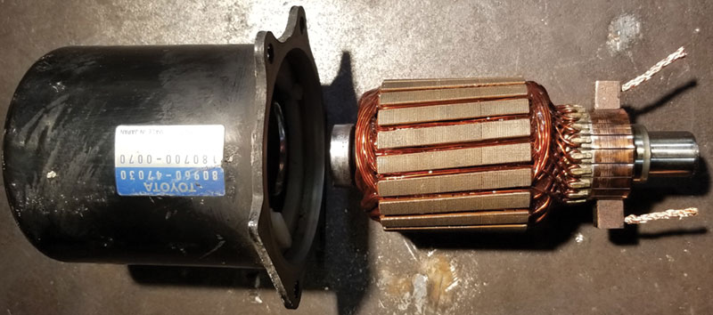
A brushed DC motor is a universally familiar design, since nearly every car in existence has at least one. Starter motors, window motors, blower motors, and wiper motors are usually brushed DC. In a brushed DC motor, the rotor is a series of electro-magnets energized in sequence to attract the energized segment to a permanent magnet of opposite polarity mounted in the motor housing. The energizing sequence is controlled by a segmented commutator ring where each end of every winding terminates 180 degrees apart. Carbon brushes transmit the voltage from the motor’s input terminals to the commutator ring.
Once energized, the rotor spins, and the next set of commutator segments is energized, and the cycle continues until power is cut. A DC motor has two terminals. If positive is applied to one and negative to the other, the motor will spin. If polarity is reversed, the motor will spin in the opposite direction.
In DC motors, the direction of assist is controlled by the polarity of the voltage applied to the EPS motor. The speed and torque output of the motor vary with current flow, which is determined by voltage level. Voltage level can be modulated by applying pulsed DC to the motor using transistors in the EPS ECU. For instance, if 14 V is available and we want to apply 7 V to the EPS motor, the EPS ECU provides a 50 percent duty cycle square wave to the motor.
Brushless DC
Brushless DC motors are really AC motors, since they are driven by 3 phase alternating current generated by the EPS ECU. A brushed DC motor will have two wires: one for positive, one for negative. A brushless motor will have 3 wires, one for each phase. Toyota typically calls the three phases A, B, and C for the EPS system, rather than the U, V, and W used for the motor/generators in the hybrids.
A brushless DC motor is driven by an inverter comprised of six transistors built into the EPS ECU. By cycling sets of transistors together, the EPS ECU energizes two phases at a time. Unlike the brushed DC motor, the electro-magnet is in the housing, not the rotor. The windings that create the magnetic field are known as the stator, since they are stationary, and are arranged in segments that are in order, much like the commutator in the brushed motor – A, B, C,
A, B, C, and so on. The EPS ECU creates a rotating magnetic field that travels around the stator. The rotor is a segmented permanent magnet with alternating north and south poles. When the rotating magnetic field is created, the rotor poles follow the poles created by the stator and the motor spins.
Some brushless DC motors have a position sensor and some don’t. A position sensor is necessary if the rotor absolutely must not turn in the “wrong” direction. When the first set of phases is energized, the rotor will turn to line up its north poles with the stators’ south poles and vice versa and then follow the moving magnetic field. The direction it jumps on start-up depends on the closest set of opposite poles.
If the stronger attraction is clockwise the rotor will jump clockwise. If the intent was for the motor to spin counter-clockwise, this may or may not be a problem. It depends on the size of the segments which will determine how many degrees the rotor spins with each step, and the amount of gear reduction which is going to have an effect on what the driver would feel in the steering wheel if the rotor took one step back before going forward. For the motors that use a position sensor, a resolver is used.
Regardless of motor type, overheating protection is often added to the system to prevent damage to the motor or EPS ECU. Motor temperature is usually estimated using amperage and time. In theory overheating protection might cause a customer complaint of temporary loss of assist with no trouble codes. In practice the driver will likely overheat long before the EPS motor does if he puts the system to the test.
DC/DC Converters
DC/DC converters are transformers, two coils of wire wrapped around a common ferrous core. When a pulsed voltage is applied to the primary coil, the resultant expanding and collapsing magnetic field induces a voltage in the secondary winding. The level of voltage in the secondary winding depends on: 1) the voltage applied to the primary winding, and 2) the ratio of coils between the primary winding and the secondary winding. Secondary voltage will be higher than primary if the secondary winding has more coils. Secondary voltage will be lower if the secondary winding has fewer coils. Transformers that increase voltage are known as step-up transformers. Transformers that decrease voltage are known as step-down transformers.
Toyota uses DC/DC converters in several of their EPS systems. Some vehicles increase voltage for the EPS motor and other vehicles decrease voltage for the EPS motor. Step-down transformers are used in some hybrid vehicles since there is a ready supply of high voltage. For instance, the Gen 1 Highlander hybrid dropped the 288 V pack voltage to 42 V for the EPS motor using a DC/DC converter under the center console. Step-up transformers are used in both hybrid and conventional cars to increase battery voltage for more efficient motor operation and better torque. DC/DC converters that step up voltage are typically located in the EPS ECU. An example of this is the Gen 3 Prius with the brushless motor. The EPS ECU roughly doubles the auxiliary battery voltage for the EPS motor, bringing it up to about 30 V.
Network Communication
The EPS ECU reads the torque sensor input directly, but it needs at minimum one other bit of data from the network to work properly; vehicle speed is the other important input. When the car is being parked, the driver needs a lot of help to turn the steering wheel, but when the car is driving down the freeway, the same level of assist would make the car feel twitchy and unstable. Vehicle speed is an important input on all cars with EPS systems.
The EPS ECU is sending and receiving more data on newer cars. For instance, the Vehicle Stability Control (VSC) system can send a torque modification request to the EPS ECU in conditions when the driver has gotten in over his head and VSC is trying to sort it out before the car is out of control. Lane Keeping Assist (LKA) will ask the EPS ECU to nudge the car back into the lane if the driver attempts a lane change without signaling. The Advanced Parking Guidance System (APGS) will work with the EPS ECU to turn the steering wheel when parallel parking. We will likely be seeing more and more systems tied to the EPS via CAN BUS as cars continue with their baby steps towards full automation.
0 Comments