

Step one; start the engine and allow to idle… It won’t start? Now it’s time to start with step zero, starting with the starter. From batteries to connectors, through the corridors of the battery cables and even the ever-controlling ECM, starter diagnosis isn’t the same old procedure it used to be. It now requires more advanced diagnostics and a few cool new tricks. Let’s take a look at modern and classic starting circuit diagnostics.
It seems like such a simple task to accomplish; make a switch turn on a motor to get that engine cranking. For most of our automotive history that’s pretty much all that was involved. A switch to turn the power on to a high amperage DC electric motor to make the engine crank. The driver would completely control the duration of the starter operation and could almost supernaturally feel when the engine was supposed to start and surely notice when it didn’t start exactly when it should.
With simplicity of control comes room for error. An extra-long cranking time would inevitably devolve into a ritualistic dance of mashing the accelerator pedal and praying over the steering wheel. And if the engine starts, then any possible problems are quickly forgotten.
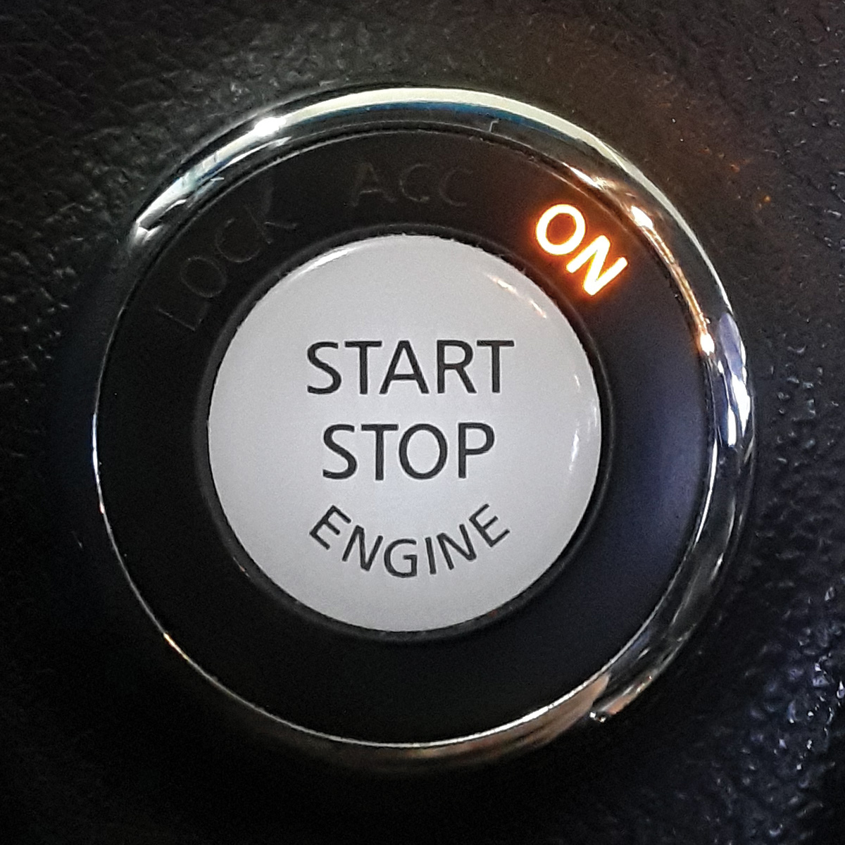
Fast forward to today. With the simple push of a button, all judgment is removed from the driver’s consideration. There is no question. If the engine doesn’t start, something has gone horribly wrong.
It’s this kind of advancement that acts as a double-edged sword. The old way of turning the engine over was so simple to understand and diagnose that even the weekend shop hand could have a go at it and probably find the solution in short order.
Starter circuits didn’t change from the first Datsuns imported to the US in the 1950s until the mid-2000s. Basically there is a keyed switch powering a relay powering the starter. Add in a park/neutral switch or clutch pedal switch for safety and that’s about it.
With the advancements in push button starting, hybrid technology, anti-theft systems, and automatic idling-stop systems, diagnostics will take much more knowledge and, most likely, an advanced scan tool. We now have to consider components like the brake pedal switch, body control module, integrated power control module, steering column, anti-theft system, and even the key fob. Now nearly all types of failures in the old system are still possible in the new systems, with the addition of many new ways for the system to fail. On the other hand, Nissan has made massive strides in improving the designs of the systems so that problems are much less likely than ever before.
One of the more interesting developments is idling stop technology. Simply put, this system kills the engine when you don’t need it at a red light. The idea is that the engine won’t use fuel if it isn’t running. There is a trade-off in that the engine will have to be started many more times in an average commute, adding more wear and tear to the starter and engine.
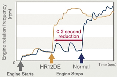
To compensate, Nissan has improved the durability of the starters and made the engine bearings more durable against startup damage. Another consideration is that the system can’t be obnoxious. When the green light comes on the car needs to move seamlessly. To that end, engineers have reduced starting time dramatically. When the brake pedal is released the engine will crank in less than half a second and start as quickly as 0.2 seconds in the case of the new Nissan 3-cylinder engine, the HR12DE. That’s roughly translated into less time than it takes to get your foot from the brake to the accelerator. Of course, this system is almost completely computer controlled with the exception of a driver override option, making it an effective feature without being obtrusive.
In the push button ignition system, one issue that can really get you scratching your head is when you push the start button, and nothing happens. The first instinct is to inspect the starting circuit and battery, or even popping the button out of the dash to test it, all because we assume the system functions the same as an ignition switch.
The button, however, is simply an input device. The failure is almost always in how the BCM responds to the button press and what other factors it’s taking into consideration before energizing the ignition and starter. Paying attention to what happens on the dash can give you the first clue to a possible answer. If the display continues to indicate, you should press the brake pedal to start the car and if your foot is firmly on the brake pedal we now have a different symptom to diagnose.
In the 2007 to 2010 Nissan Altima there is a known failure in the stop light switch that prevents the BCM from recognizing the brake pedal position. In such cases a TSB and installation of an improved switch design can resolve the issue. Most any model with a push button ignition can have switch failure cause a no-cranking condition. You can confirm the brake signal is getting to the BCM with a scanner and data stream to be certain, but simply verifying that the brake lights work may give you your answer faster.
Another failure we are seeing with the push button start is in a safety feature that can sometimes malfunction. With the removal of the actual ignition key we also removed the ability to mechanically lock the steering wheel. An electronically controlled locking mechanism in the steering column was adopted to fill the gap. Since this system is integral in the ignition system, a failure in the lock mechanism or steering column control module can cause a no-crank condition.
In this case the steering lock position is not correctly relayed to the BCM and IPDM, so it defaults to an off or locked position. Often this will be accompanied by erratic steering column lock functionality. In such instances you can tell the lock is partially engaged but it’s not really locked all that well.
Although the steering column lock module can fail on its own, aftermarket devices (for remote start, alarms and such) connected to the system have been known to cause these kinds of failures. Diagnosis for this condition is going to start with a Consult III Plus or other scanner that can communicate with the BCM when the ignition is off. Stored codes for steering lock failures are likely going to point you right to the problem.
Several systems all have to work together, each doing their part to get the engine to crank when it’s supposed to. In early systems the ignition switch would send voltage through a neutral safety switch or clutch pedal position switch, then power the starter solenoid and the engine would crank. With the introduction of the relay, the system gets a little more advanced in that we now have multiple conditions that have to be met for the starter to engage.
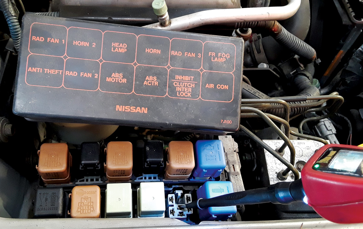
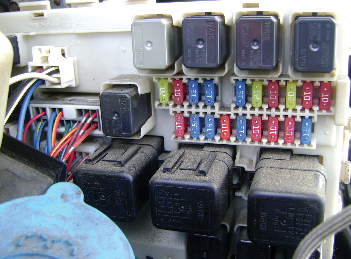
Let’s take the example of the 2000 Nissan Maxima. A relay labeled as the “park/neutral position relay” in the wiring diagram (Inhibit/clutch interlock in the relay box) is the main control relay for the starter. Neither the relay, nor the signals to it, are computer controlled with the exception of the anti-theft module supplying battery positive to the control side of the relay.
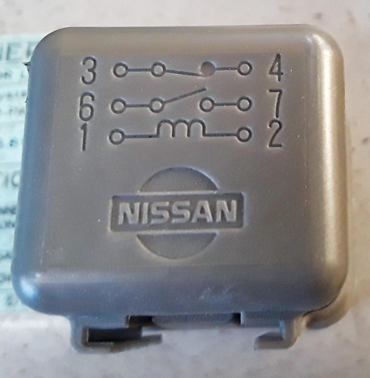
In a much appreciated move, Nissan engineers designed the relay with the actual wiring diagram printed right on the relay. What’s more, it’s actually labeled with the same pin identification numbers as the service manual wiring diagram. Following the wiring diagram, you can quickly identify which signal is missing to get the starter to engage. For example, pin 7 is the direct wire for the starter solenoid. By applying battery voltage to this pin, the starter should engage (making sure the transmission is in Park or Neutral of course). In one step, and with minimal labor, you’ve eliminated half the possible causes of your no-crank condition and you’re in the right place to test the other half.
Moving forward in the generations, the starter circuit gets much more involved. Each control module has its own function in the starting process. The BCM sends the signal to the IPDM to activate the starter relay, the TCM sends the signal to the BCM that the transmission is in Park/Neutral, the IPDM directs the power through the starter relay to the solenoid, and the solenoid on the starter supplies the motor with current to crank the engine.
More advanced systems work on basically the same principle, with added modules sending information to the IPDM and BCM until all the signals needed are present. This is how we end up with a failing brake light switch preventing the starter from cranking. The major benefit to the system working this way is that we can communicate with the BCM and determine exactly what signal is missing.
On the engine side of the IPDM or relay box a whole other set of safety precautions should be taken with any starting system diagnosis. The amount of torque and amperage going through these starters is astounding. With modern gear reduction starters, 90 amps on a no-load bench test is normal. Even the tiny 1.8L Sentra starter without gear reduction can still draw over 50 amps, and that’s not even counting the drag of the engine and start up amperage. That’s also enough amperage to melt an 18 AWG wire and open the fuse in your multimeter instantly if testing is not conducted properly.
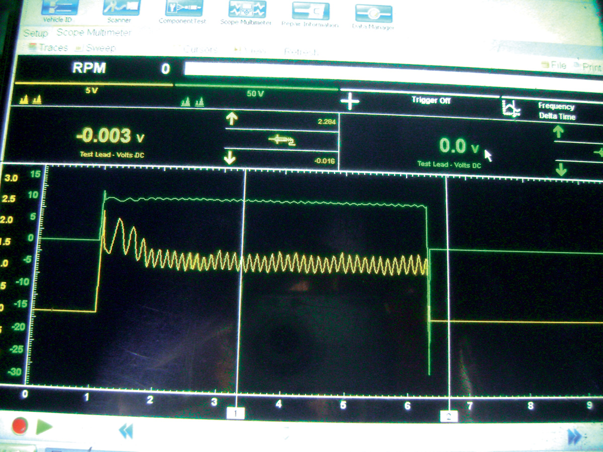
When the shop manual says “disconnect the negative battery cable,” it’s not kidding. The main power supply cable from the battery to the starter is not protected by a fuse and is capable of delivering enough power to really hurt you, melt the cables, or weld a wrench to a body panel. Testing amperage is very useful and should be done with an inductive amp probe only. Checking the integrity of the starter amperage waveform with a graphing multimeter can identify failing windings by an erratic “hairy” pattern even when the starter sounds like it’s working well.
The same caution must be considered when addressing a dead battery. If time permits you should always charge the battery separately as opposed to jump starting or boosting a battery just to get the vehicle running. In some vehicles, especially hybrids, the 12 volt battery is the AGM type (Absorbed Glass Mat). Nissan recommends that AGM batteries only be slow charged. Because jump starting vehicles is relatively common it is sometimes not given the cautious attention it deserves. Accidentally connecting a booster battery (or worse another vehicle) backwards, even for an instant, can cause devastating damage to the electrical system, fuses, fusible links and even damage various control modules, especially the intelligent power distribution module.
Jump starting hybrids isn’t all that different than on non-hybrids, and can be even easier and safer in a lot of cases. Take the Nissan Altima hybrid for example. The 12 volt battery is under the trim panel in the trunk of the car. Fortunately, there is a connection under the hood that can be accessed without the added risk of hydrogen gas built up by a nearby charging battery. If you’re not sure about the connections, stop and look it up. The approved jump-starting connections are easy to find in the service manual and also in the owner’s manual. Just remember, in any hybrid, orange marked cables are off limits. Don’t touch them.
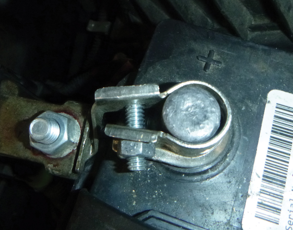
Don’t forget to keep it simple to start with. The noise you hear when you turn the key should give you a pretty good idea where you need to look. If you hear a rapid ticking coming from the engine you need to start by checking for adequate voltage at the battery and starter. You should expect somewhere around 10 volts while cranking and higher than 12 volts when not cranking. In particularly cold climates not only are battery failures commonplace, but so is corrosion on the battery connections and ground points, either of which can keep a starter from cranking.
After the battery is confirmed adequate with a load test, a good test to verify that your battery cables and connections are good is called a voltage drop test. Connect a multimeter negative lead to the starter end of the battery cable and connect the positive end to the positive battery terminal, then crank the engine and watch for a reading of less than 0.5 volts. Any more and you know you have excess resistance in the wire. Then repeat the same test for the ground side. Resistance can hide in wires and connections that look good.
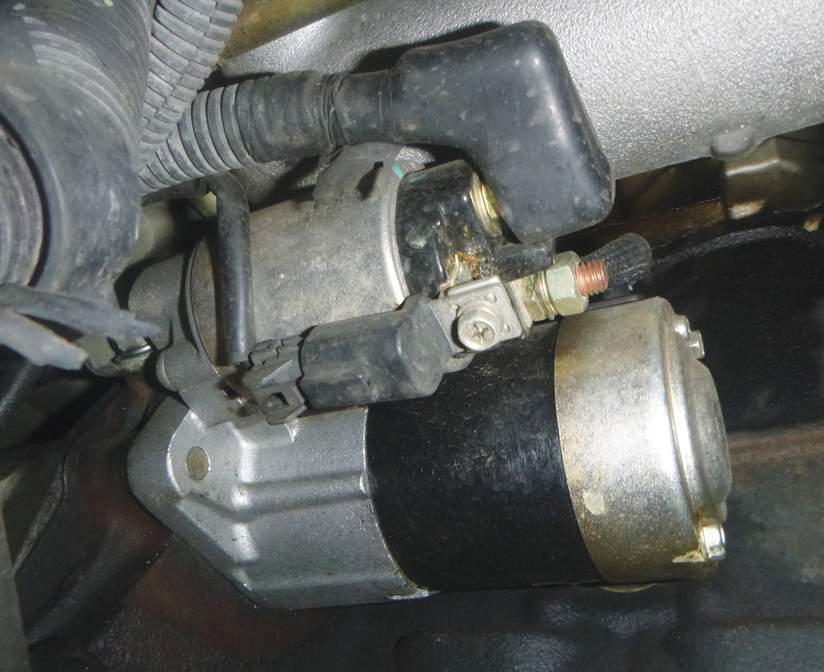
Once the power supply and cables are confirmed, take a moment to make sure the engine will actually turn over by hand. Replacing a starter only to find out the engine is seized is not a mistake you want to make. If you have access to test the starter directly with a power probe, energize the solenoid with battery voltage. If there is still no cranking, it’s time to take that starter out for a good old fashioned bench test.
If you’ve never done this test before, be advised that the torque in these starters is impressive. Secure it in a vise, snug but certainly not crushing the starter case, or just strap it down to keep it from jumping off the work bench. Connect a known good 12 volt battery with the ground to the starter case and power to the battery cable connection on the solenoid. Then, using a power probe or jumper wire, energize the switch connection of the solenoid (sometimes called terminal “S”). If all you get is a clicking from the solenoid, the test is over, that starter is toast.
Even if the starter turns on the bench, test the current the starter is using. Gear reduction starters can pull up to 90 amps, and non-reduction models about 2/3 of that. There are standards available for each application in the service manual if the readings appear close to failure. Also note any unusual noises. It shouldn’t sound like a blender, just a smooth, powerful electric motor. The gear should thrust out when the starter first engages and stay engaged firmly until the power is removed. Any signs of weakness mean it’s time to replace that starter.
The starting system can present a very frustrating system failure for your customer, as it leaves no leeway for their busy day. In today’s world of overbooked schedules, a funny noise in the suspension will often be ignored and a squeaky belt will frequently be put off, but a failure to start can leave anyone from a business executive to a soccer mom in a panic. Being efficient in your diagnosis and getting your customer back on the road ASAP will go much further in these desperate situations. A quick solution will make you the hero and may earn you a customer for life. Taking the time to learn and understand the starting systems is a great way to increase your value as a technician as well as keeping our society on the move.


0 Comments