
From time to time, you may get that certain vehicle in your bay that has many small issues that need attention, but there’s usually only one big driveability problem that prompted the customer to visit your shop. Often these vehicles are doing things that seemingly defy logic, and sometimes seem to defy physics as well.
These are the vehicles that can make technicians lose sleep some nights.
Today, with the sheer onslaught of high technology in engine controls, management systems, software coding, rationality codes, plausibility algorithms, ADAS systems, and CAN packets that can’t be easily decoded for quick diagnostics, automotive technicians are having to take in a ton of technical service information. It’s so intense it has literally become like trying to drink water from a fire hose year over year.
These vehicles are showing up in our bays with more and more complex issues every day. From ADAS systems, to GDI, CAN network issues to mechanical engine problems, as techs, we’ve got it all coming at us these days.
As such, in order to remain relevant now and into the near future and grow diagnostic skills as technicians, you must engage in constant study and experimentation and seriously accelerate your in-depth study of basic electrical principles and electrical system diagnosis. Scan tools and DTC charts can no longer be your only diagnostic option.
The failure to do so will likely render many of us irrelevant, seeking retirement or possibly even unemployed as techs in future years. How do we solve this dilemma and stay sharp on diagnostics?
Enter the concept of physical testing
Using a lab scope, some out of the box diagnostic strategy, and leaning on basic electrical testing principles combined with some high-tech strategy, we can be far more accurate and productive in our diagnoses, especially on these tougher driveability issues in gasoline direct injected vehicles, which often present with no codes.
Combine lab scope physical testing with pressure transducers that allow you to evaluate the internal engine quickly and accurately without engine disassembly and you have a game-changer for diagnosing modern day vehicle platforms.
Here are a set of tests that, once learned, can be applied to any 4-stroke vehicle and used in several creative ways to get diagnostic answers without much concern at all for the technical complexity of the platform you are working on.
This testing method can be taken from vehicle to vehicle and it can be the same test method on each car being serviced. This greatly simplifies the diagnostic path and nearly ignores the complexity of the car.
Another huge benefit is that using this testing methodology, you can greatly reduce your computer research and schematic lookup time, and in fact, almost eliminate it in some cases.
This testing methodology does NOT seek to circumvent prudent research for DTC flow charts and TSBs in the diagnostic process, however. You still have reading, research and due diligence that go with any proper diagnostic procedure, but this research time can be greatly diminished in most cases.
Yet these techniques are often not being leveraged by OEMs, dealers
or independent repair shops.
Why? Because the word is just getting out on the street, and mostly in the independent repair market. There are an increasing number of shop owners and techs now paying serious attention to this new diagnostic approach, and for very good reason.
With this waveform, you can determine running engine compression, camshaft timing and phaser operation, piston movement, piston ring health, valve leakage (huge in catching GDI engine misfires), vacuum, exhaust back pressure and much, much more.
All on one screen, using the same simple test for every car
Add to this a signal overlay strategy, and you now have a visual confirmation that the PCMs, electronic sensors and signals are in perfect time (or not) with the actual movement of the inside of the mechanical engine. In the past, this has been technicians’ “great unknown.”
And you can do these tests, even on the most complex engines, usually in ten minutes or less, without taking any of the engine apart.
For the first time, you now have a way to verify, quickly, whether or not the electrical and mechanical systems are working properly in sync.
Once you learn how to leverage this waveform imagery and strategy in your diagnostics, rarely will you see a tech return to the “traditional” diagnostic methodology. Why, you ask? Because you can find and fix driveability issues using this method so quickly and accurately, you just never want to go back to the old ways.
Today, technicians need to be able to blend diagnostics into several broad subject areas, for example:
- You need to be able to diagnose mechanical internal engine issues, transmission and powertrain issues.
- You need to be fairly advanced today in your knowledge of electricity and electrical transport systems.
- You need to understand telematics and ADAS systems that interface computers and programming to the actual mechanical operation of the vehicle and, You need to be part psychic and soothsayer.
The reason we need to be all of this? All of these systems now fully interface and interact together in today’s platforms. This new testing method accommodates all of that.
So how do you productively and, more importantly, accurately diagnose these multiple integrated platforms without expensive diagnostic mistakes?
You can apply these new testing strategies to your existing mix, and really improve your accuracy, and time to fix.
But what is meant by the term “physical testing?” Physical testing involves testing the electrical system’s transport systems (wiring) between points to pinpoint the cause of a problem. It also involves mechanical testing of systems. These two areas are inextricably intertwined in modern diagnostics.
OK, so what can physical testing and a basic electrical testing focus do in such a high tech business, you ask? Everything. Literally, everything.
When you put your hands on the vehicle and perform lab scope tests, you can hook up multiple affected circuits, watch the behavior of electricity (this is the key) in the circuit and catch errant and intermittent electrical behavior.
You can track down the problem quickly and accurately using this method, and once you learn what you are doing with these tools and methods, you can substantially cut down your research, schematic lookup and computer time and improve flat rate efficiency as well.
The best part? Good, accurate diagnostic calls, consistently. Consider this case study as an example:
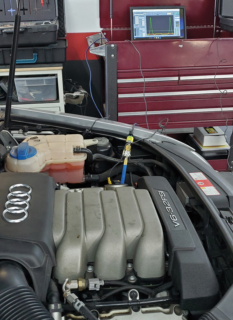
A 2009 Audi A6 came into a shop with a distraught (and almost broke) customer. The car had an ugly history of diagnostic and repair work that had been done, but that had not yet resolved the customer’s concern, and he was in deep (financially and frustration-wise) with this car.
Originally, the vehicle presented with multiple misfire DTCs, a MAF Plausibility code, a series of cam/crank correlation codes, and an Exhaust Camshaft Retard Set Point Not Reached code.
All of the possible external parts had been “tried” on this vehicle, and the result of several service visits and parts replacements was that, while the misfire codes were “almost gone,” the vehicle still had a power loss issue, and the car was still setting the Exhaust Camshaft Set Point Not Reached code.
It seemed that the variable valve timing camshaft phasers that were installed by the dealer had solved the other two timing-related DTCs. But the new MAF sensor did not cure the plausibility code. Hmmm.
The diagnostic approach was to drill into the history and look closely at the history of the case. The problem was apparently still in the mechanical timing due to the idle shake, loss of power, and Exhaust Cam Retard Set Point code that still existed.
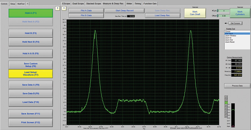
Further diagnosis involved the installation of a pressure transducer, connecting the vehicle to a lab scope and studying a running compression test on Bank 1 of the engine. Measuring the camshaft timing showed that, though it was very close to spec, the intake camshaft was out slightly by a few degrees.

Time to measure Bank 2


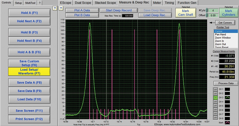
The second image shows that the camshaft timing is WAY out. The intake cam is out by 30 degrees, and the exhaust cam timing measures out by 60 degrees. This explains the Exhaust Cam Retard Set Point Not Reached code, the loss of power, and the MAF plausibility code.
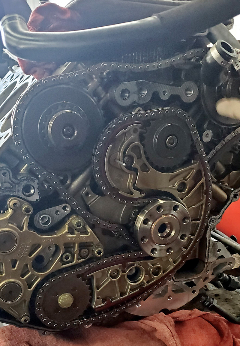
Because the timing chains on this engine are between the engine and transmission, it is essential to be accurate with the diagnosis because the customer had spent so much money already, and it was apparent that the engine needed to come out for repairs.
The scan tool, believe it or not, is just one tool used in this process. A scan tool generally would be used to provide data, codes, and clues as to where to look for the problem, or as a tool for actuation, measurement and maybe programming software too. This works well on average if the computer is telling us the truth. Yet we’ve been leaning on this as the primary diagnostic method for decades.
As an industry, we are beginning to see an evolution in diagnostics. With the costs of parts, modules, and labor going ever higher for the driver-consumer, this diagnostic gap is a serious issue for the sake of our customers’ wallets, and our local reputations as quality repair shops.
Because most of us were trained in one way or another to track down a driveability or diagnostic problem using a scan tool, DVOM and a DTC chart, many technicians learned diagnosis via the “trial by fire” method (“Here kid, take this scanner, plug it in here, and do this procedure…”).
“Old Uncle Joe” in the bay next to us also told us “how things were done” and showed us how he solved the problems of his day. Between that advice, and our own diagnostic growth path, most of us have kind of stumbled through learning diagnostics, learning more and getting smarter at diagnostics as we go along in our careers.
The concern beginning to show up in shops today, though, is that many of us, by virtue of how we learned our way into diagnostics, also bypassed basic electrical training, the kind that teaches us how electrons flow, the kind that teaches both AC and DC electrical principles and diagnosis.
This (unknowingly) could be our industry’s biggest weakness, servicing modern-day vehicles using 1980s diagnostic strategy and methods.
The moral of the story?
Don’t be afraid to look at and try out new diagnostic ideas and, for goodness’ sake, be enthusiastically willing to look at some of these emerging diagnostic technologies.
In the next article of this series, we will build on this technology and show how to utilize this waveform with a signal overlay strategy to complete the electrical/mechanical diagnostic relationship.


0 Comments