
Diagnosing today’s transmissions can be a complex task, especially when it comes to transmission driveability issues. In transmission diagnostics there are a multitude of factors involved, some mechanical, some electrical, and then there are other factors, such as hydraulic pressures, PWM duty cycling of control solenoids, friction coefficients, Push Belt theory and fluid health.
Suffice it to say, a good transmission diagnostic tech must have a fairly broad knowledge of theory in each of these areas in order to accurately nail down the cause of an issue.
This discussion will focus on the electrical diagnostic methodology involved with the transmission’s sensors and control solenoids and also discusses the general procedures required for successful replacement of the valve body assembly in a Nissan CVT vehicle.
Why successful replacement, you ask? Most all modern electronically controlled transmissions require either “learn in” procedures, programming, or dynamic road testing (or all of the above in this case) to successfully match the transmission, its components, ROM, and modules (TCM), and then initialize communication with other modules on the network so that the unit can be controlled and monitored.
Nissan transmissions, whether CVT or Step-Shift, are no exception. If a sub-assembly of the Nissan transmission is replaced and is not relearned, programmed or coded properly (depending on year and model), the vehicle may experience either no-go driveability, shifting problems, harsh engagements, slippage, MIL lights, DTCs… you get the picture!
Since the diagnosis of either a CVT or Step-Shift unit is essentially the same from an electronic and electrical standpoint (electrical control of hydraulic pressure circuits), we use a 2013 Nissan Altima with a CVT transmission as an example car for this discussion*.
Due to the fact that there are so many makes, models, years and transmissions out there, this diagnostic discussion follows a generic solenoid diagnostic path, as outlined in Nissan’s published service information for a P0778 Transmission Fluid Pressure DTC in an “average” Altima type car.
There are typically four to six separate solenoids in a typical Nissan valve body, depending on year and transmission model. Whenever you are diagnosing one of these valve body/solenoid control DTCs, always use the appropriate service information for that particular year, make and model.
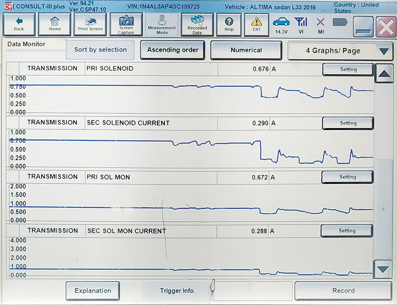
In this example, a lab scope is used in conjunction with the Consult III Plus data to view sensor and solenoid behavior during diagnosis. The scope is also deployed for another critical test specifically used to find the fix on this car.
Lab scopes are simply a visual volt meter that charts voltage, current, or pressure activity (vertical axis) over time (horizontal axis). As such, a technician can quickly “see” circuit and load problems while the vehicle is operating the circuit. This is a tremendously valuable thing: to be able to see what the electricity is doing in the circuit, watch the load’s behavior and measure the circuit’s parameters.
Using a scope, we can view the waveform, check power feed and ground circuits, verify reported scan data, and check motors, sensor circuits, switches, relays, and loads. More importantly in this case, we can voltage drop test the entire circuit, from the power supply side, through the load, and back to ground, visually.
When combined with OEM guided DTC charts, schematics, and a good grasp on system theory, this testing method is invaluable, because it provides the technician a complete picture of the circuit in operation. This approach is often far more valuable in terms of exposing circuit problems as compared to the standard non-loaded voltage potential checks and continuity tests on static circuits, wires, or loads that are usually called for in DTC flow charts.
A recent case study on a similar 2012 vehicle was solved using this diagnostic method and the lab scope, after the transmission had needlessly been replaced by another shop for a recurring trouble code. The lab scope, combined with the use of the CONSULT III Plus, a schematic, and the DTC information, helped to identify the fault and repair the vehicle quickly.
What would likely be the most important first step a technician would want to take in this kind of diagnosis?
Without question, this should be a search for TSBs on the issue or complaint.
Why? Because the amount of coding and programming (number of lines of code running) in the average control module is staggering these days, and just one single errant 0 or 1 in the programming can lead to driveability problems we can feel, but can’t mechanically or electrically fix. Programming solves some mysterious driveability issues that otherwise may not be solved.
It is always good practice to search TSBs first and follow bulletins’ OEM instructions accordingly.
Now, consider that this Altima comes into your bay with a DTC P0778 or similar DTC related to Pressure Control Solenoid B
Electrical Fault. Solenoid B is the secondary control valve solenoid.
This DTC will set if the TCM detects that normal voltage/current is not applied due to “cut line, short or the like.”
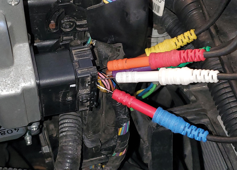
Now is a great time to rig the scope.
On this vehicle, the TCM is conveniently located right next to the battery, with plenty of room to work. The benefit of testing the circuit here is that the technician is essentially testing and voltage dropping the complete circuit, including the wiring to the controller. That’s fast and productive work.
The TCM detects the P0778 fault by comparing the B solenoid’s target value to monitor value. This fault will be set based on direct feedback from the solenoid B circuit itself.
When diagnosing a P0778, you can monitor this current difference yourself by comparing ISOLT3 data PID and the SOLMON3 data PID. These PIDS are looking at the secondary valve solenoid current performance, displayed in amps.
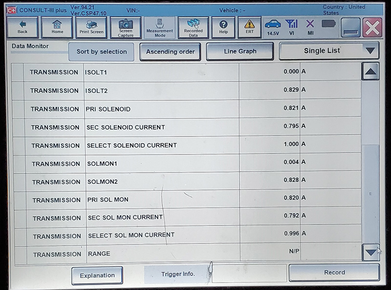
In kind, the ISOL2 data PID and SOLMON2 are used to check the line pressure solenoid performance. Service information states that, with foot off the throttle idling, ISOL2 should read 0.8 A, and when throttle is depressed to the floor, reading should be 0.0 A.
ISOL1 and SOLMON1 are used for monitoring TCC solenoid performance, on and off states (lockup off, 0.0 A, and lockup on 0.7 A).
So back to the Altima to flow the diagnosis:
A quick look at the Nissan’s P0778 DTC flow chart first (step 1) has the technician preparing the vehicle by driving slowly up to 31 mph, holding that speed for at least five seconds in Drive. Then the chart asks whether or not the DTC was detected.
Yes, it was.
Next, the focus of the DTC P0778 flow chart is directed to step 2 in the diagnostic procedure: checking out the secondary pressure solenoid valve.
To check the secondary solenoid the tech is directed to the diagnostic procedure, where he must disconnect the TCM electrical connector F-16 and check resistance between connector terminal 39 and ground. This essentially checks to see if the wiring or solenoid inside the unit is shorted to ground.
You perform this test and find that the resistance is correct; the ohmmeter reads
6.5 ohms (spec is 3.0-9.0 ohms).
Next step (3) in the test is to check continuity in the harness, by disconnecting the TCM and CVT harness connectors and measuring the resistance of each wire. The chart indicates that continuity should exist end to end on the wire. Does it have continuity? YES.
So next (step 4), they have us checking circuit 39 in the harness (only) to ground, and the chart says continuity should NOT exist. Does continuity exist? NO.
Good… onward and upward. Next (step 5), the tech is directed to check the continuity of the internal transmission sub-harness in the same fashion, end to end. Does continuity exist? YES.
And the final step in the chart: Check the internal harness cladding (insulation) for damage. Is there any damage? NO.
At this point, depending upon whether you are chasing a P0868 or P0778 code, you either arrive at “intermittent” and must re-test endlessly into the failure, or are now directed by the test chart to replace the transmission, valve body or TCM, (depending on year and model), so you replace what is indicated.
Upon replacing the unit, and following the required learn-in and programming procedures (to be detailed in Part 2 of this article) you are shocked to find that the same condition exists. Same code, same condition. OH, NO!
What went wrong here? You were sure you followed the steps properly, so you go through it again. Same result!
Now, THIS is why it is important to understand the electrical principles behind what we are being asked to test here. What went wrong in this case? Was this really a mis-diagnosis? Can you guess what possibly went wrong here, and how it went so wrong?
Let’s go back and review the step where you were asked to check continuity in the harness, between the CVT and the TCM. If you tested the wire with an ohmmeter, it beeped and showed 0.1 ohms. This passed the test step, so we can move on, right? Or is this where we may have been inadvertently led astray?
Consider this: If you had a 16 or 18 gauge wire that the TCM uses to drive voltage and current to the solenoid, and if 11 of the 12 strands of that wire were broken, would that wire show good on a continuity test?
Yes, of course. If there is one single strand left with a good connection, the ohmmeter will beep and show 0.1 ohms, a pretty perfect reading.
But would that damaged wire be able to carry the CURRENT required to operate that solenoid? Nope. Not a chance.
So what happened in the case of the Altima’s repeat P0778?
It could be reasonably argued that the guided test procedure itself could have, at the very least, not only contributed to, but likely indeed caused, the technician to miss the real problem with the vehicle, which was a broken solenoid wire in the harness with a couple of strands still connected.
How can technicians avoid this kind of unfortunate miss and get it right the first time?
Simply remember that in all cases, when testing a wire, it needs to be able to carry current to run that load in operation, not just beep the ohmmeter! Therefore, a well-studied tech will always perform voltage drop testing on these circuits before making the judgment that the circuit is good or bad. A continuity test is never sufficient to judge the wire as good. Never.
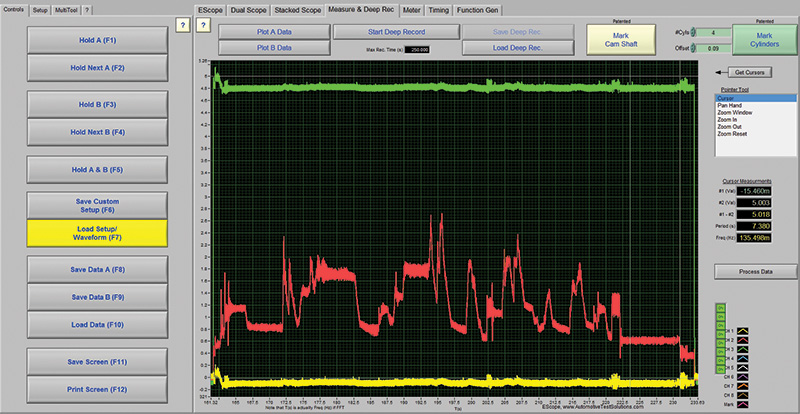
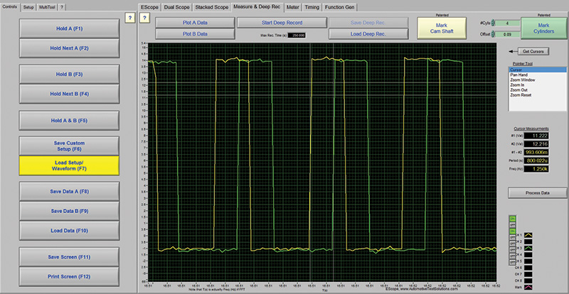
Voltage dropping is the only way to confirm that a circuit is actually able to perform, period. And the lab scope lets us voltage drop visually and instantly see whether the drop is on the power or ground side of the circuit.
If the voltage drop occurs from the bottom of the waveform (lifting off the 0 volt ground line) then the drop is occurring on the ground side of the load. If the waveform drops the voltage from the power line at top, and the ground stays steady, then the drop is on the power side of the load.
This test is much more cumbersome when done with a voltmeter; the visual on the scope is powerful for productivity.
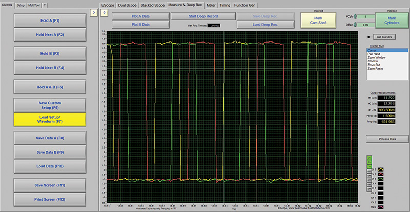
The solenoids are pulse width modulated to control duty cycle required to direct sufficient pressurized transmission oil to the sheave pulleys. This is why you can observe that all three solenoids are being driven and duty cycled at the same rate, at almost exactly the same time. The reaction time from command to movement of the sheaves is a mere 800 microseconds between each (less than one millisecond).
The scanner/scope method and the voltage drop test, generally, represent an incredibly fast and efficient way to “see and solve” the circuit. Why are new and experienced technicians alike not taught voltage drop as a critical diagnostic test right out of the gate?
Now that the electrical code is solved, we need to replace the valve body. Nissan calls the valve body a sub-assembly of the transmission, and the valve body is now replaceable. In older models, the technician was directed to replace the CVT unit. Now, in later models, the transmission sub-assemblies can be serviced and replaced independently from the entire unit.
To change the valve body in this CVT, the general instructions are to disconnect the negative battery terminal and pump out the CVT fluid from the charge pipe. Next, remove the transmission electrical connector and connector snap ring and press the connector into the transaxle case.
Then, remove the transmission oil pan, remove the nut, washer, manual valve plate, and collar. Next, disconnect the internal harness connectors, then remove the strainer filter and bracket.
Finally, remove the control valve’s bolts, and remove from the vehicle, making sure to disconnect the CVT unit connector and lip seal from the transaxle case once the control valve is loose.
To install the new control valve, after replacing the connector lip seal and re-connecting the internal harness with the stopper facing up and pushing until it clicks in, simply reverse the removal procedure and fill the unit with fluid.
Note: Be sure to use new gaskets, pan bolts, and o-rings per the published service procedures, and be sure to torque the new bolts in proper sequence as directed for each model.
To complete the repair, the vehicle will need to have three operations performed to initialize the transmission.
The control valve (valve body) ROM memory must be cleared, the CVT Fluid Degradation Level Data must be cleared and, depending on the actual sub-assembly repair you do, the TCM and valve body may need to be programmed and initialized. Finally, before driving, one of three possible “learn in” procedures, either Pattern A, B or C, must be performed.
Part 2 of this article will continue the transmission diagnostic discussion with a focus on testing pressures, and will cover the after-repair functions. Part 2 will detail all of the necessary TCM programming steps (both J-2534 and CONSULT III Plus) and transmission re-learning procedures, as well as drive patterns and when to use them. Read Part Two.
Much appreciation to Tony, Ishmael, Ryan and Rick at Bowie Nissan in Bowie, MD for their kindness in helping with the vehicle and CONSULT III Plus for this article.
The CVT Push Belt Theory
 On CVT transmissions, there are two primary types of metal chain style belts, and some vehicles (very few now) use a rubberized belt in place of the metal chain.
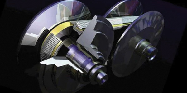
Most CVTs run what is known as a “Push Belt” or metal band, which is made up of about 400 little steel plate links, stacked together (think in-line, like a tractor tread kind of setup).
Those little link plates are held in place by stacks of very thin flexible steel bands so the belt can flex and turn around pulleys. You can envision these bands as similar in material and size to the metal bands used by factories to bind shipping pallets together… thin bands of flexible metal.
Some chain belts have nine little flex bands stacked up in grooves on either side of the metal plates, and some higher horsepower engines require a CVT belt with 12 bands for increased strength. The bands engage, and hold together, the outsides of the belt plates and guide them, so to speak…
Now, as the push belt rolls around the circumference of the pulleys, the little plates relax, separate, and kind of “fan out” to accommodate the movement around the curved part of the pulley.
But when the push belt comes off of the curved part of the pulley, the little plates “snap back” together, causing an effect similar to that of a solid steel rod. This “rigidity” and the angular bevels on the plates allow the belt to push the driven pulley, rather than a conventional belt, which would essentially “drag or pull” the pulleys around, causing them to turn via friction. Hence the term “push belt.”
Note: a conventional “pull” belt is very inefficient mechanically speaking, as compared to a push belt.
In push belt theory, the drive device (the pulley connected to the engine, the primary pulley) actually does less physical work. This is because the rigidity of the belt and tapered edges which ride in the pulleys are actually what cause the friction needed to drive the driven pulley (the secondary pulley), which is connected to the final drive, then off to the wheels.
The push belt also has its little plates machined with beveled edges similar to those in a conventional V belt. This is the mechanism that allows the metal push belt to smoothly run up and down the beveled pulleys while they are being clamped and released by oil pressure to change gear ratios.
Another kind of metal CVT belt uses articulating chain links that slide in and out to create the same push belt action. But rather than having 400 little plates, this belt looks and acts a bit more like a modified bicycle chain, with beveled chain connectors that slide back and forth, creating the “relax” part needed for going around the pulley.
The third style of CVT belt is a tapered rubber belt with much more strength, weight and tension than a typical V belt.


0 Comments