

It is often a moment of considerable discomfort for many technicians when faced with the message on their scanner, “No Communications.” Usually, it is accompanied by other complaints that may range from troubles in the operation of controls like HVAC, power mirrors, backup camera, turn signals, etc., since almost every output in modern vehicles is now controlled via some kind of network-based signal.
In our study today, we will be troubleshooting a no-crank, no-start complaint on two different vehicles; a 2006 Nissan Pathfinder and a 2010 Nissan Frontier, both equipped with the 4.0 L engine and the automatic transmission. While the vehicles are representative, the troubleshooting procedures described have been shown to be effective across a range of manufacturers and vehicles.
Let’s begin with a brief overview of irritating words that tend to create confusion, since the words themselves are non-intuitive, at least in the opinion of this author. Let’s start off with the word “protocol.” The vehicles we want to look at in this article are equipped with the OBD CAN protocol. Because of the “OBD” designation, we know we can depend on certain things being true, since they are dictated by CARB regulations relating to on-board diagnostics.
First, it will be a two-wire network (there are single wire networks that use the CAN protocol, but they are not OBD). Second, there will be two 120 ohm resistors found on each “end” of the network (end is in quotes because the star topology that we are looking at next technically doesn’t have “ends,” only the linear topology). Third, the CAN high or positive waveform will be roughly from 2.5 to 3.5 volts (Nissan deviates slightly on this one by adding 0.25 volts on both), and CAN low or negative will be from 2.5 to 1.5 volts. This is a very big help as it is true of all OBD CAN networks.
Of note here is that many technicians are unaware that non-OBD CAN networks are not required to conform to these standards and therefore non-emissions modules may have a waveform signature quite different from that on the OBD CAN network. Fourth, the DLC (Data Link Connector) will communicate with the scan tool on pins 6 and 14.
Next, we have to consider the other non-intuitive word “topology.” See Figure 1 for a typical Nissan CAN network topology.
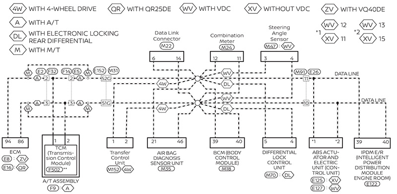
Note that this vehicle is equipped with what we call a “star network.” In other words, each module on the bus is connected to the others and to the DLC via a common splice, so that every module has an independent path back to the splice and then a shared line back to the data link connector.
Unfortunately, Nissan does not locate the 120 ohm resistors in the diagram, but in our experience (and as we will see on both vehicles we analyze in this article), one of the resistors is always located in the ECM. An alternative configuration, used by Nissan in a “hybrid” (combination of more than one type of topology), is the linear topology, preferred by some manufacturers such as GM. Figure 2 is a typical linear topology as found on a 2014 Chevrolet Malibu.
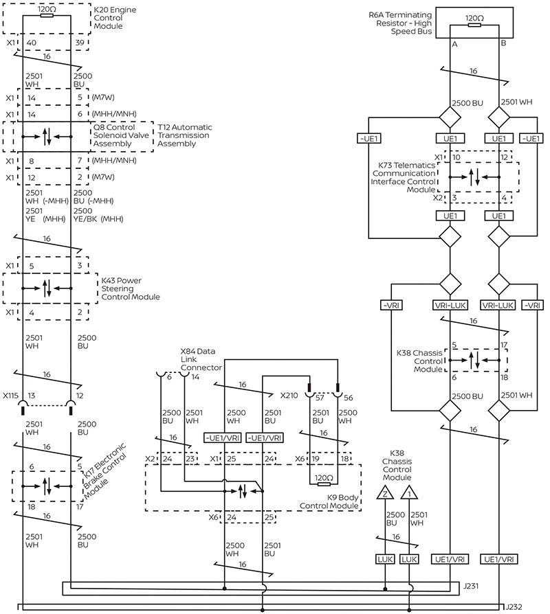
The reason the topology matters for troubleshooting purposes is as follows: If the ECM on the Malibu needs to communicate with the BCM for purposes of validating the key code, for example, that communication must pass through the TCM, PSCM, and EBCM. There is no alternative; so, if an open exists in one of those three modules, the vehicle will not start and communication may be lost with several modules. However, on the plus side, GM sets module-specific communication codes which can be a great help.
For example, in the scenario supposed above, if the PSCM was open circuit, we would likely have these specific codes in both the EBCM and the BCM: U0130 (lost communications with the PSCM), and U0100 (lost communications with ECM). Those codes can really help point us in a direction as to where the trouble lies. Note that the modules with the codes are rarely the modules with the problem, since more often than not, the failed module is incapable of telling on itself. An exception to this sometimes occurs when the module in question communicates on two different networks; it can code for itself by reporting on the network that functions.
More sophisticated Nissan and Infiniti vehicles use the linear topology configuration to connect two, or sometimes three, star networks. You will need to bear that in mind should you have a need to troubleshoot one of these vehicles. The vehicles we are troubleshooting today have a single star network.
So, now that we have that messy stuff out of the way, let’s dig into our first problem vehicle, a 2006 Nissan Pathfinder 2wd with a no-start, no-crank complaint. We will start with defining our diagnostic strategy for OBD CAN networks in general.
First, we scan all modules to see who is talking and who isn’t. Presumably the scanner function of “scan all modules” will execute this automatically, but we have found that sometimes it doesn’t work that way with aftermarket scanners. To ensure that a module not scanned in the mode of “scan all modules” is checked, always try to scan modules individually if they do not show up on the list of scanned modules.
Second, we will identify the network topology via the wiring schematic and see which modules the vehicle has or should have. Sometimes this is harder than it sounds due to different configurations of options or, as some manufacturers like to call it, “as-built” or “RPOs” as in “Regular Production Options.”
Third, we will disconnect the battery and check the network resistance. We do this between pins 6 and 14 since our OBD protocol guarantees us that those two pins will be the two wires; CAN high or positive on pin 6 and CAN low or negative on pin 14.
Our next step, not always necessary if we find something in the previous step, is to look at the network waveform with a scope. This job can be done with a voltmeter, but it is far from the preferred method.
Our (hopefully) last step is to start disconnecting modules to isolate the issue. The trajectory of our diagnosis is often predicated on our findings in each step, so hopefully looking at two real-life cases will illustrate this well, starting with the 2006 Pathfinder no-crank.
The “scan all modules” function on our Pathfinder scans four modules, three of which have codes.
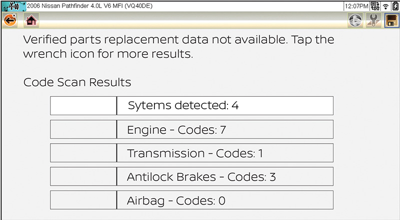
The network diagram indicates all modules that could be on the vehicle, assuming it is equipped with all options. Our vehicle is a stripped model so let’s look at the network diagram to see how many modules should be showing up on the scan.
Our vehicle is not 4wd, so we don’t have a transfer case module. Next, because this is a stripped model, we do not have a driver’s seat control unit or a Display Control Unit. But we should have all of the following: ECM, TCM (AT), Meter, BCM, Air bag, SAS (Steering Angle Sensor), ABS, and IPDM. Instead, we have only ECM, TCM, ABS, and Air bag.
Our next step is to see which codes we have. Unfortunately, Nissan often only provides us with the generic U1000 code. We also note (without surprise) that we have a P1612 NATS code which is to be expected without communication with the BCM. An additional code registered is the P1212 TCS (Traction Control System) communications line. This code, along with others registered in the ECM memory, are what are called “sympathy codes,” and are very common distracters when troubleshooting network problems.
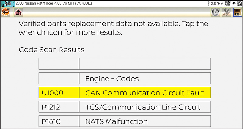
Inexperienced techs sometimes get sidetracked by these codes, but consider this description under Nissan service information for the P1212: “If DTC P1212 is displayed with DTC U1000 or U1001, first perform the trouble diagnosis for DTC U1000….” Thinking it through, traction control is executed when the ABS module detects wheel slip on acceleration and has to interface with the vehicle ECM in order to reduce throttle plate position, or possibly retard the spark, or even shut down injectors. When there is a communications fault, obviously this system would be disabled and therefore these “sympathy” codes will set.
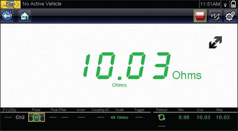
So, as our codes are not much help, we move on to our next step, which is to check the total network resistance. While this doesn’t always help, in this case we realize we have found an issue indeed. The number should be 60 ohms, since the mandatory two 120 ohm resistors are wired in parallel in the network wiring. While individual additional modules put a very slight parallel load on the circuit, their resistance is typically so high that the 60 ohms remains virtually unaffected. However, our reading is not 60 ohms, but 10 ohms.
We are definitely onto something here. It might be a shorted wiring problem, but that is somewhat unlikely since there is some communication going on with the bus. A short would almost certainly bring the whole bus to a screeching halt. A scope check was probably not necessary, but curiosity is often a helpful trait in the auto technician development so a scope check was done.
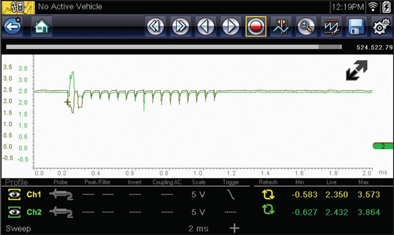
This pattern is about as far from a good OBD CAN as one can get, but ironically there are still four modules capable of communicating.
Typically, one would think that the problem would be with one of the non-communicating modules. That is indeed what we thought and we began the tedious job of accessing and unplugging the non-communicators. None of them improved our 10 ohm reading, so we proceeded on to check the modules that were communicating.
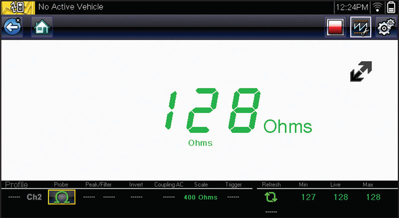
The air bag module was communicating, and when it was found (inconveniently located below the center console) with red paint markings typical of salvage yard parts, it was unplugged with considerable anticipation and corresponding disappointment when no change was noted. But, as things sometime go, it wasn’t until the ECM was unplugged that the resistance returned to the anticipated 120 ohms (actually 128).
A used ECM was sourced and plugged in. Resistance was rechecked.
Extra trouble was encountered in overcoming the anti-theft system due to the use of a used ECM but, once that was overcome, the vehicle started and ran normally with all modules back online.
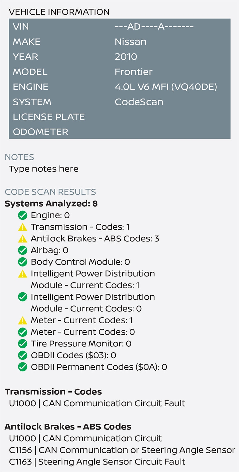
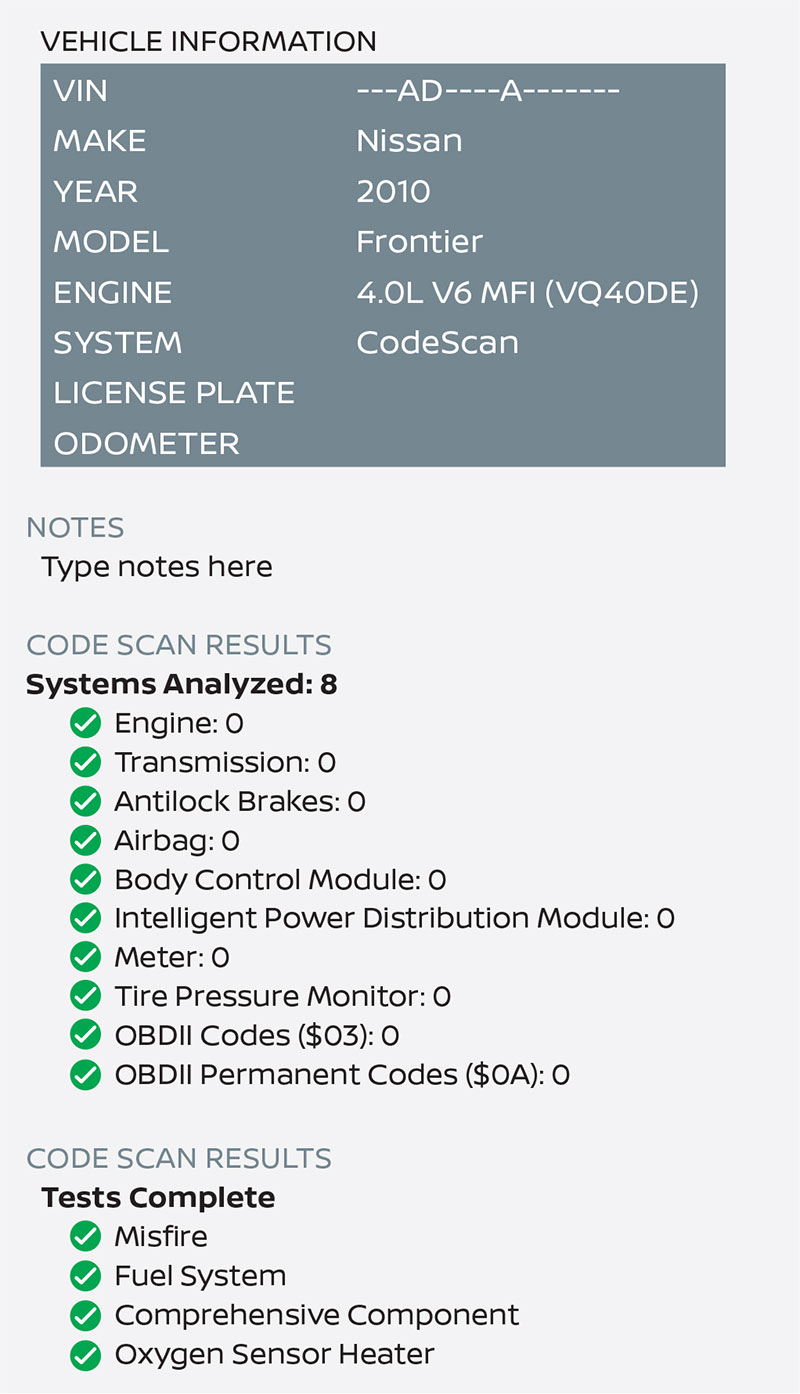
Moving on to our 2010 Nissan Frontier with an identical complaint of no-crank, no-start, we started with a scan of all modules. The following report comes from the Snap-On software known as ShopStream Connect.
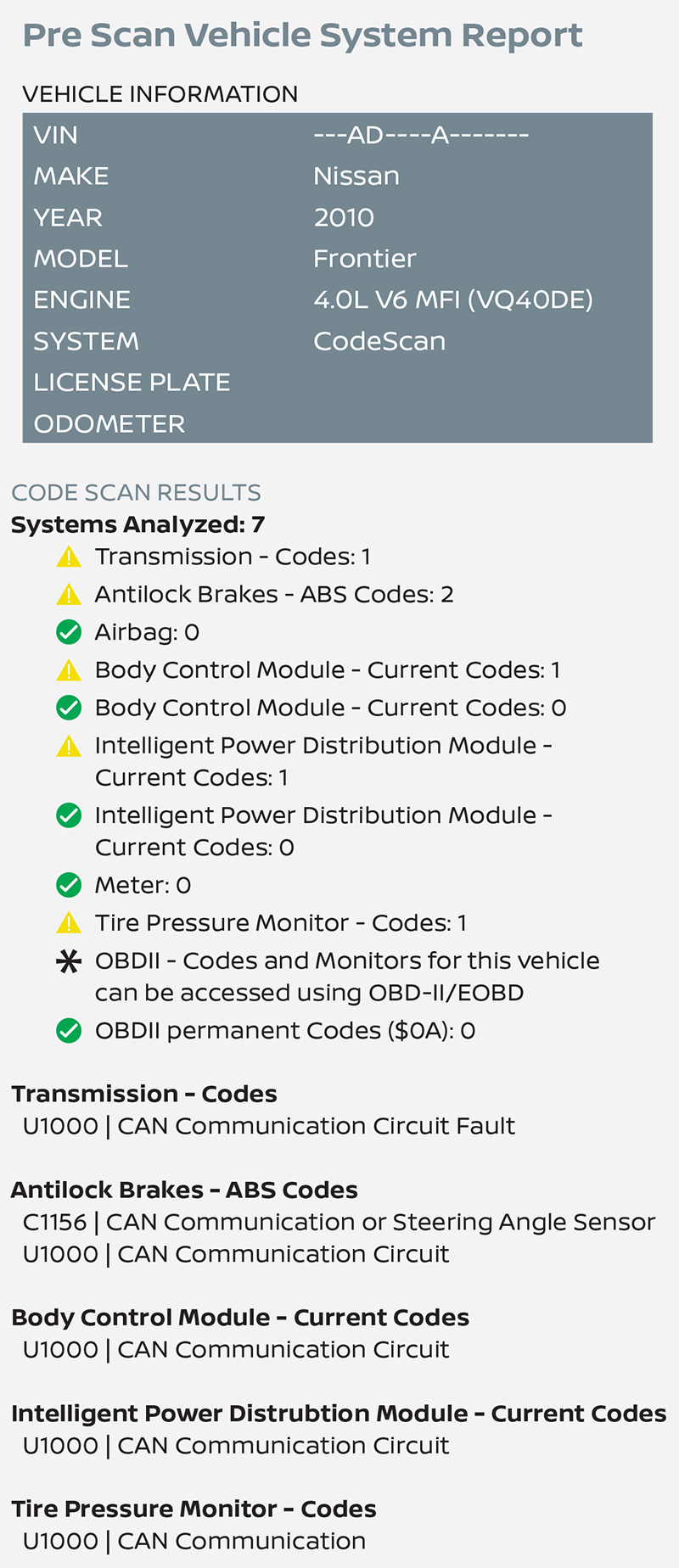
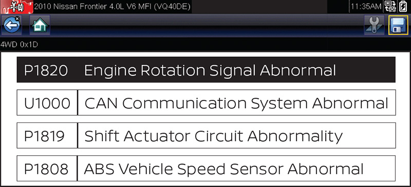
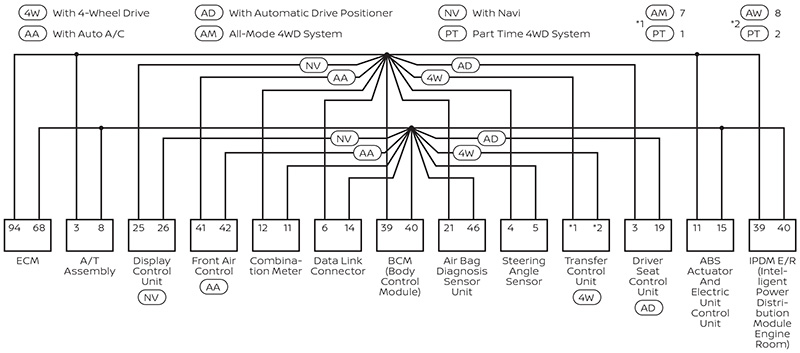
Seven modules are reporting, and five of them have our U1000 code; but our model is a 4wd and should have shown a 4wd module (see Figure 10). Scanning it independently, we found that it communicated just fine, in spite of being missing from the all-module scan (see Figure 11). Why this was the case remains a mystery, but it may just be a mistake in the Snap-On software. We looked up the network topology (see Figure 1) and found that it could have a differential lock module. An inspection under the rear of the vehicle confirmed that this model DOES NOT have the differential lock. What was obviously missing from our scan was the mandatory ECM. Attempting to communicate with it gave us the “No Communications with selected module” message.
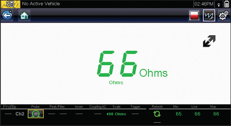
Following procedure, our next step was to disconnect the battery and check the resistance between pins 6 and 14. But this time we did not find similar success as compared to the last vehicle. Resistance was dead on at 61.9 ohms. To confirm the ECM has a terminating resistor, we went ahead and disconnected it and remeasured resistance as illustrated in the photo (see Figure 12).
Our next step was to scope the OBD CAN bus signal and this time we were rewarded with a problem signal. Note particularly the fact that the rest voltage is NOT at 2.5 volts and not even very close to it. Also, CAN high and CAN low should be identical to each other. They were most assuredly not (see Figure 13).
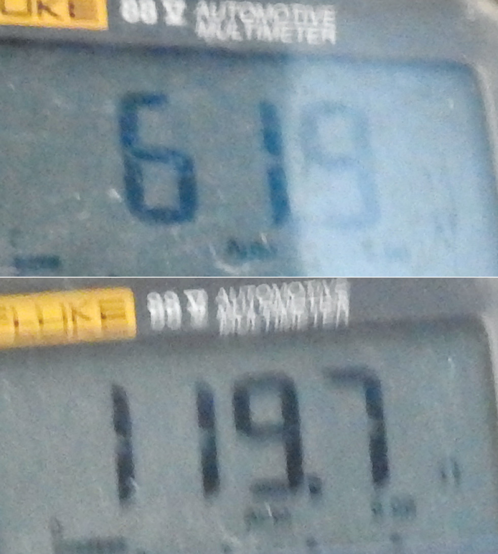
For those of you not equipped with a scope, we have provided voltmeter readings to show the difference between CAN high and CAN low with the ECM connected and then disconnected (see Figure 14). When deciding whether or not to replace a component valued at over $1,000, it is nice to have the scope readings as opposed to only those from the voltmeter, which gives us an average. Even the high-speed Min/Max feature of the Fluke 88 Series 5 meter is no match for the very fast CAN network. Notice the time base on the data capture; there is only 1 ms on the entire screen.
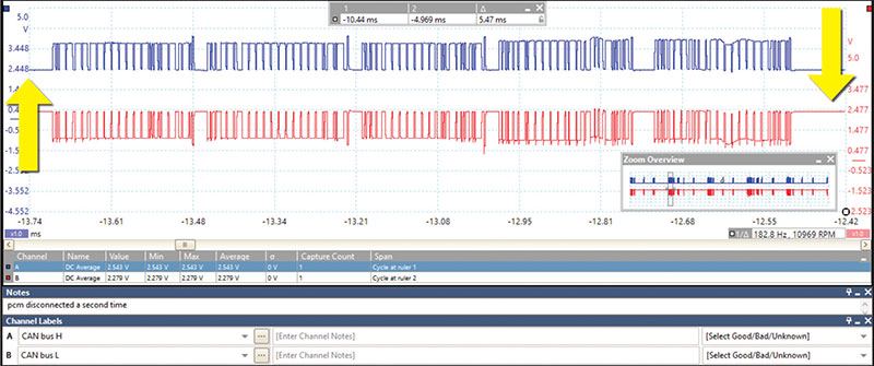
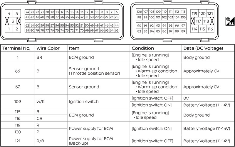
Figure 15 shows the waveform with the ECM disconnected. Note how the voltage levels at rest are very close to the 2.5 volt OBD CAN standard. You can also see the slight Nissan non-conformity with the 3.5 and 1.5 volt standard.
Of necessity, we have to add one additional step before we spring for the ECM replacement; confirmation of the powers and grounds. Missing grounds can distort the ECM CAN bus signal and it just isn’t worth the risk to skip this step. We did not do that step on the previous vehicle because a missing power or ground would have had no effect on the resistance reading, and recall that we had abnormally low resistance. Figure 16 is the table used to check powers and grounds (which were found to check OK).
This time, in order to avoid the misery experienced with the used ECM on the last vehicle, a new ECM was sourced from Nissan. A VIN write and programming were performed using NERS software and a subscription to the Nissan website (a subject for a different article). A rescan was performed afterwards and some concern resulted from the results (see Figure 17).
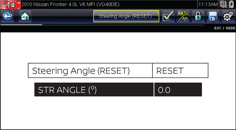
Was the SAS faulty? Why does the TCM show a U1000? It was feared that we have missed something, even though the vehicle started and ran just fine. A resetting attempt of the sensor was made (see Figure 18).
After the reset, a final scan confirmed all codes were resolved (see Figure 19).
To recap the procedure used in just a short paragraph: Scan all modules; determine the modules that should be responding on the bus in question via network topology; check the CAN bus total resistance; scope the CAN bus high and low; proceed with module disconnection and power and ground confirmation, as required. Isolate faulty module or network wiring and repair or replace as needed.


0 Comments