


Does the word “Infotainment” make you cringe? Well you’re not alone. A lot of technicians are nervous about working on these systems, but they’re not as bad as you may think.
The first part of the word “Infotainment” is “Information,” and that’s what you will need to master these systems.
The fact is that you will probably never be able to master all these systems because of the fact that they are always changing. New systems and functions are coming out a few times a year these days.
Volvo’s newest infotainment offering is called Sensus Connect. And with its large tablet-based control screen, it is one of the most advanced and most connected systems on the market today. Everything runs through the Sensus system and the driver can customize everything.

The Sensus has three ways for the driver to interact with it — touch screen, voice control, and it even has a way to read our handwriting.
In the aftermarket we are not really dealing with these Sensus cars yet, but they are right around the corner, and if you don’t keep up with new technologies you will be left behind.
Have you ever had a customer come into the shop with a complaint of something not working right, just to find out that the customer did not know how to use a particular feature or function of their vehicle?
Of course you have. And this is probably happening a lot more lately. That’s because, over the years, in-car features and technology have become increasingly more advanced, and the number of tasks that your car can perform has increased exponentially.
It’s like getting a new phone for most people. The new smart phones can do so much, but most people only know how to use about 30% or 40% of their phone’s features. On infotainment systems like Volvo’s Sensus Connect, the phone features only represent about 10% of what these systems can do.
The point is that, as these systems get more complex, you will not only have to fix them, but a lot of your job will become customer education.
When you get some of these newer Volvos in the shop you should take some time to “passively” play with some of the functions and capabilities of these remarkable infotainment systems. Of course, try not to change any of the driver’s personal settings, but get to know these systems so you can educate your customers.
You or your service writer will have to interview the customers that have these later Volvos to determine if the issues they are experiencing are actually a problem or just user error or user lack of knowledge.
When diagnosing problems with Volvo infotainment systems you are going to need to have Volvo’s VIDA software and a DICE tool. You may be able to check parts of the systems with a newer high-end scan tool, but VIDA is the only tool that will get you there in any kind of plausible time.
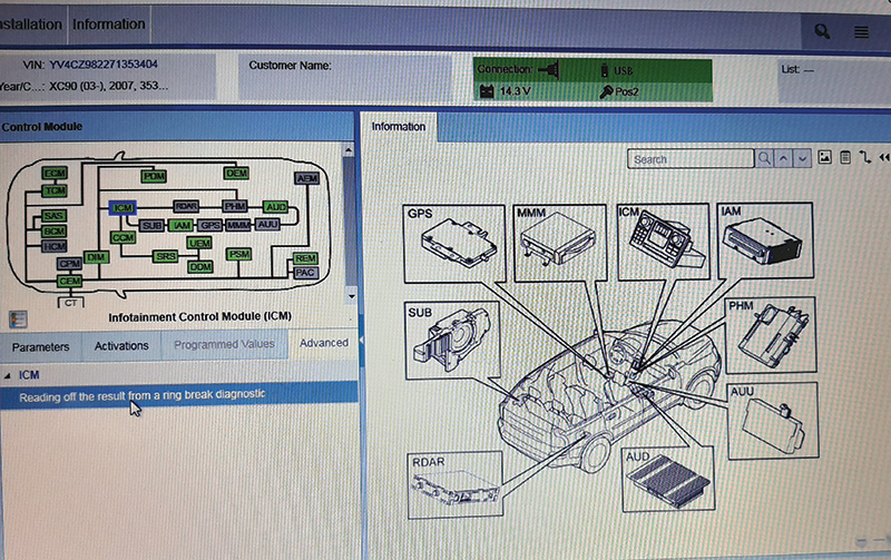
VIDA has a powerful diagnostic tool when it comes to the MOST network. The MOST ring break test will help you quickly and effectively test the MOST fiber optic network.
The wide range of Volvo infotainment systems would be much too large to cover in this one article, but we will touch on a few common issues.
When dealing with Volvo infotainment issues, you should always make it a habit to check for Technical Journals or TJs. You may find that some issues can be fixed with just a software update.
Below is the abridged Technical Journal (TJ 34021.1.1) that may help you avoid a common mistake that many technicians have made.
SiriusXM Radio inop or NO Sound on SAT
| Source |
|---|
| REF: No: TJ 34021.1.1 |
| Issuing Department: Technical Service |
| FUNC Group: 3900 |
| FUNC DESC: Media, navigation and communication |
| ISSUE DATE: 2018-08-08 |
| STATUS DATE: 2018-09-18 |
Vehicle Type
For affected vehicles, refer to Service Manger Bulletin 00-013 for a types cross reference.
CSC Customer Symptom Code
| Code | Description |
|---|---|
| 2P | Satellite radio/Does not work |
DTC Diagnostic Trouble Codes
Rows beginning with * are modified
NOTE: If using a printed copy of this Technical Journal, first check for the latest online version.
Description:
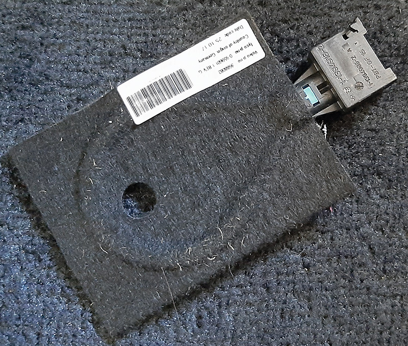
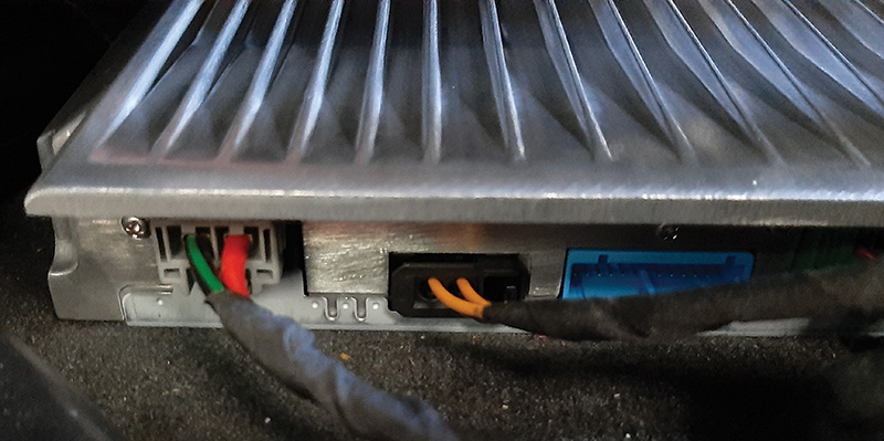
RDAR = Remote Digital Audio Receiver
The customer may report no sound on the Satellite Radio source or that Sat radio is inoperative on any channel.
If a new or known good RDAR unit is plugged in, it will work normally. However, after mounting the unit, it may become inoperative immediately or after a period of time (several days or weeks).
SERVICE:
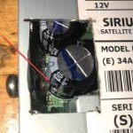
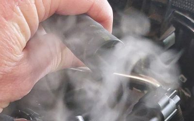
Check the length of the RDAR mounting screws. If too long a screw is used in the mounting hole closest to connector “A” on the RDAR, it can make contact with and damage one of the internal capacitors (see image on right).
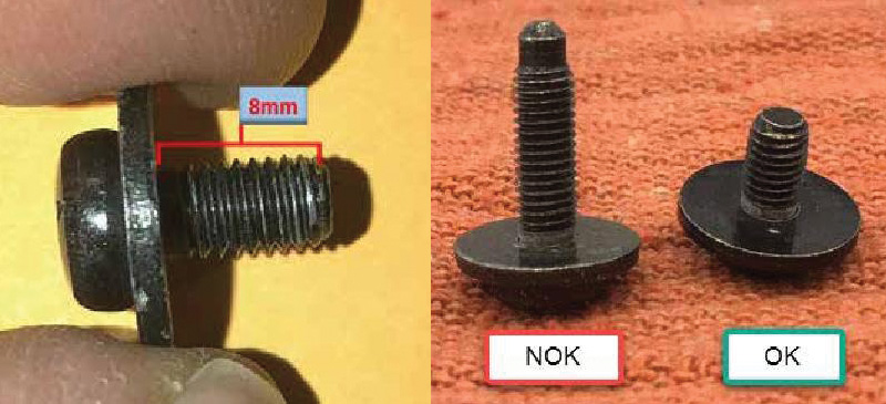
The screws should be no larger than M5 x 8 mm in order to avoid interference with the internal components of the RDAR.
At the bottom of this post is a Volvo service bulletin that will help you diagnose a very common Key Off battery drain issue with some of the cars that use a satellite radio receiver.
What does MOST mean?
MOST (Media Oriented Systems Transport) is a high-speed multimedia network technology optimized by the automotive industry. It can be used for applications inside or outside the vehicle.
The serial MOST bus uses a daisy-chain topology or RING and Synchronous data communication to transport audio, video, voice, and data signals via plastic optic fiber (MOST25, MOST150) or electronic connectors (MOST50, MOST150) physical layers.
MOST technology is used in almost every car brand worldwide, including Audi, BMW, GM, Honda, Hyundai, Jaguar, Lancia, Land Rover, Mercedes-Benz, Porsche, Toyota, VW, SAAB, Skoda, Seat and, of course, Volvo.
Fault tracing MOST networks
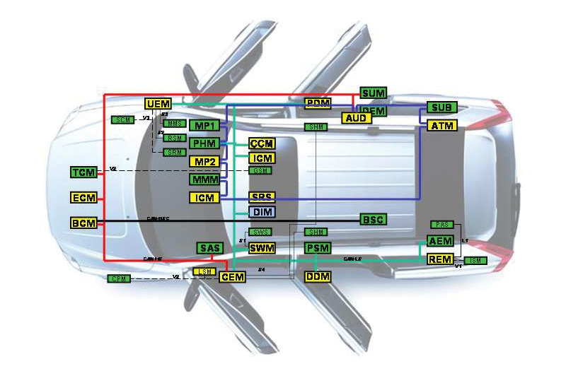
The ICM has detected an open circuit in the MOST network. The MOST network is a fiber optic ring network. This means that all control modules, which are connected to the network, must be powered and grounded for the infotainment system to work. If a control module for any reason is unable to receive or send signals on the MOST-net, or if there is an open circuit on the fiber optic line, then the ICM will shut off all functionality.
Communication on the fiber optic net is one-directional. The control modules on the MOST-net receive the light signals, amplify them, and then send them on. The MOST connectors for the control modules contain two fiber optic cables — one for incoming and one for outgoing signals.
If the fault is intermittent, it has been registered previously but is no longer present. Intermittent faults can be caused by interference at start-up of the MOST network (ECM), or can be a different type of fault which occurs on different occasions. The fault is evaluated depending on how it occurs. If the fault recurs, fault trace for permanent faults.
An intermittent fault may be difficult to diagnose using ring break diagnosis because a condition for this is that the fault occurs while the diagnostics program is running. If the fault is permanent, perform a ring break diagnosis to locate the open circuit.
Fault management on the MOST network
General: The MOST network is monitored by the ICM. If it detects a fault in the MOST network, a diagnostic trouble code is stored in the infotainment control module.
There are different types of DTCs depending on the type of fault. A general rule is that, if the light pulse in the MOST network disappears, the entire network stops working.
Fault types which are processed are:
- No communication from a control module.
- Faulty communication on the MOST network.
There may be no communication from a control module. The ICM knows which control modules are connected to the MOST network. If any control module on the MOST network ceases to communicate, a diagnostic trouble code is stored in the ICM. There is a DTC for every control module on the MOST network for this fault.
Missing communication may be due to an internal fault in the control module or because the function
is incorrectly implemented in the control module.
Faulty communication
For faults when messages cannot be sent on the MOST network, DTC ICM-U1A2400 is stored.
Causes of this fault may be:
- A control module, except the infotainment control module, has a defective optical connector.
- A control module has an internal fault which means that the optical connection stops working.
A control module on the MOST network is not powered. If there is no power supply, the optical connector stops transmitting light. - The optical cable is damaged or there is an open circuit. This fault can occur if the bend radius of the cable is too small or if the cable is kinked or trapped.
- There is dirt or oil on the optical connectors which impedes the light.
- The connection to a control module has come loose.
- The fiber optic terminals in the connector are cross-connected.
- There is a loose connection because the fiber optical wiring is incorrectly installed, or the fiber optic terminal pin has been pressed back in the connector.
- A bridging connector has come loose or is damaged.
Ring break diagnostic procedures are used to remedy DTC ICM-U1A2400. If a break is discovered in the MOST network after running a ring break diagnostic procedure, DTC ICM-U1A1587 will be stored in the ICM. If this is the case, you can determine which control module the open circuit is located in by reading off from the ICM.
Ring break diagnostics

General: This function is important when fault tracing the MOST network. Ring break diagnostics are used when there is an open circuit in the MOST network and DTC ICM-U1A2400 has been stored in the ICM.
Ring break diagnosis means that all control modules send a message to the ICM in reverse order of how they are located in the MOST-net. This means that Accessory USB Unit (AUU) sends first and not last (this applies to S80/V70/XC70, for XC60 Remote Digital Audio Receiver (RDAR)/Digital Audio Broadcast Module (DABM).
The control module which is not working will not transmit a response to the ICM. This also means that the control modules which are connected before the defective control module will be unable to transmit a message to the ICM.
The same applies to open circuits in the optical cable in the MOST network. No control module before the open circuit will transmit a message to the ICM. By using the incoming messages the ICM can identify on which control module the open circuit has occurred.
Hint: It is important to know which control modules are connected and in which order they are connected in order to know which control modules lie before and after the indicated control module.
Example for S80/V70/XC70
A MOST network contains all eight control modules. There is an open circuit in the cable between the Phone Module (PHM) and the Audio Module (AUD). See the MOST ring break illustration above.
In a ring break diagnosis the ICM receives replies from the control modules on the MOST network. Those located before the Audio Module, such as the Phone Module, cannot transmit their reply to the ICM.
The ICM now receives a response from all control modules except the integrated Phone Module, and therefore identifies the control module which is first in the loop, and which responded — in this case, the Audio Module.
If there was no open circuit, the ICM would have responded “OK.”
RDAR = Remote Digital Audio Receiver (satellite radio tuner)
This TJ replaces TJ25950 and previous versions of TJ26188.
| Code | Description |
|---|---|
| LM | Battery/Dead battery |
| LN | Battery/Weak or low electrical power |
| FC | Audio other/Other audio problems |
| DP | Radio/Does not work |
| 2P | Satellite radio/Does not work |
Vehicle Type
For affected vehicles, refer to Service Manger Bulletin 00-013 for a types cross reference.
There is no need to replace the RDAR due to:
1. No function, Locked condition:
- Not possible to select SAT1 or SAT2 as an audio source.
- SAT1 or SAT2 may be visible, but there is no reaction from the system when selecting them.
- It will not be possible to access any Sirius menu items.
- This Locked condition in combination with other factors may result in a higher than normal standby-current consumption. DTC 0008 or U300098 (overheated) may be set.
Analysis of units returned to TMA shows that almost all units could have been recovered. Software is now available to prevent this condition from recurring.
1A. To recover P1 and XC90 units:
- Remove the fuse or the power/ground connector to the RDAR and reinstall after ten seconds.
- Perform an RDAR upgrade with VIDA. This will recover the unit and prevent the condition from recurring.
- It will now be possible to select satellite radio as an audio source. An Updating Channel List message will be displayed.
- If there is no active subscription, the procedure is complete. Channel 184 may become visible or the Updating Channel List message may remain as long as there is no active subscription. Both conditions are normal.
- If there is an active subscription, the unit should be refreshed by entering the 12-digit Sirius ID and clicking on Send Activation Request at care.siriusxm.com/retailrefresh_view.action while the vehicle is running, the audio system is on, and you have a clear view of the sky. The web page will display the message “Activation Request Sent.”
After a few minutes, the vehicle will receive the signal, the channel list will be updated, and audio will be available on the channels included in the subscription. If the web page displays the message “Please enter a valid ESN,” even though the correct ESN was entered, there is no active subscription.
NOTE: In addition to the 12-digit Sirius ID being on the unit itself, it can also be found in the Warranty Inquiry screen for some vehicles where the original unit has not been replaced previously.
1B. To recover P3 units:
- It is normally not possible to recover the unit using VIDA on P3 cars.
- Lift the luggage compartment floor, unplug the power/ground connector to the RDAR and plug it back in after ten seconds.
- Copy the 12-digit Sirius ID number printed on the label.
- Have the vehicle running, the audio system on, and you have a clear view of the sky.
- Go to care.siriusxm.com/retailrefresh_view.action, enter the ESN, and choose “Send Activation Request.”
The web page will display the message “Activation Request Sent.” After a few minutes, the vehicle will receive the signal and SAT1 and SAT2 will be selectable. It will be possible to tune to channel 184.
There may or may not be audio on channel 184. This is dependent on the hardware variant and is normal.
Any abnormal current consumption issue caused by the RDAR will be solved.
If the web page displays the message “Please enter a valid ESN,” even though the correct ESN was entered, this method will not work for the particular ESN; proceed to 1C.
Once the unit has been recovered, perform an RDAR upgrade which will prevent the condition from recurring.
If they like, the customer can call Sirius and purchase a valid subscription as usual.
1C. Only necessary if 1B does not recover the unit:
- Call the Sirius/XM Dealer Support (800) 852-9696, press 2.
To minimize confusion, use these exact instructions when speaking to the agent:
- State that you would like to “Add a receiver to an engineering account and send an Engineering Restore signal.”
- You will be asked for the 12-digit Sirius ID No.
- You will be asked for the account number: 112762201932.
- You may be asked for an address: 1 Volvo Drive, Rockleigh, NJ 07647.
- You may be asked to tune to channel 184. This will not be possible due to the current state of the unit; ask the agent to send the signal anyway.
- The agent should now be able to add the receiver to the account and send the Engineering Restore signal.
If the Sirius agent is unfamiliar with this procedure, you may have to assist them.
The exact steps the agent needs to follow are:
- Click on the blue “plus” symbol (+) next to “Overrides.”
- Type in “ENG” (in capital letters).
- Click on “Override Promo Code.”
- Click “All Audio Packages.”
- Scroll down to “Engineering Restore” (it must be exactly “Engineering Restore,” nothing else).
- Choose “Next.”
After a few minutes, the vehicle will receive the signal and SAT1 and SAT2 will be selectable.
An Updating Channel List message may be displayed or the display may be blank.
Once the unit has been recovered, perform an RDAR upgrade which will prevent the condition from recurring. The fault is now repaired; any abnormal current consumption issue caused by the RDAR will be solved.
If they like, the customer can call Sirius and purchase a valid subscription as usual.
RDAR recovery 0.2 hrs 36004-2 software download — See VST
2. Specific channels are not available: This can be caused by the Sirius channel lock settings in the vehicles menu as described in the owners manual.
3. A total vehicle stand-by current draw of approximately 60 mA which drops to under 25 mA after a key cycle. This draw is triggered when the power feed to the RDAR module is interrupted for a short period of time (a few seconds) and then reconnected. This often occurs during the fault tracing process — for example when the battery cable is temporarily disconnected to insert an ammeter, when a fuse is pulled and reinstalled, when the module is unplugged and plugged in again, etc… The draw disappears after a key cycle.
The procedure for checking Stand-By current is found in VIDA:
- Information->Fault Tracing->General Diagnostics and Tests->311 Battery
- A portion of the procedure is attached
4. An RDAR unit may need to be replaced:
- If the unit can not be brought online according to the above, and after review by Prior Approval Department.
- For an internal DTC that can not be erased.
For other confirmed functional issues, as agreed with the Prior Approval Department. Refer also to TJ 25130.
This information is also published in SMB 39-001 and PB 39-001.
5. Confirm that the vehicle is not affected by other known stand-by current issues:
- C70: Battery drain due to Convertible Roof Module (CRM), see TJ 24318.
- P3: Too high quiescent current may drain the battery, see TJ 23515.


0 Comments