


This article is going to cover what Volvo would call a classic car, as the first C70 that came out in the U.S. market was introduced in 1998. It came in two configurations—hardtop coupe and what many people think was Volvo’s first convertible model. Well folks, Volvo did make a very small production run of convertibles in the early days.
Volvo’s first foray into the top-down sports car market was the P1900. It was made with a custom fiberglass body from 1956-1957.
You probably will never see one in your shop because only 68 were produced.
The purpose of this article is to educate you about problems and repair procedures on early Volvo C70 (1998-2004) windows and doors, which can be more challenging and complex than most other Volvo models.
These cars are older but there are still a lot of them rolling around out there, especially the convertibles.
When working on these cars, you should use extra care because the plastic parts can be brittle and break easily.
You may have to move or disassemble other parts during the repair. Be sure to confirm availability of replacement parts with your local Volvo retailer. Such parts might include door weatherstrips and seals, which might be difficult to remove during disassembly.
History
Volvo unveiled the first generation C70 at the 1996 Paris motor show.
They followed by introducing it into the European market as a 1997 model, and a year later as a 1998 model in North America with a low-pressure turbo (2.4 L) and a high-pressure turbo (2.0 L and 2.3 L) turbocharged engine.
The C70 broke Volvo’s decades-long styling tradition of boxy, rectilinear designs and was Volvo’s first luxury coupe since the 780.
According to Peter Horbury, Volvo’s design chief from 1991 to 2002, “With the C70, Volvo threw away the box, but ‘kept the toy inside!'”
Volvo’s vision was to design a convertible that would meet the needs of a family of four looking for comfortable blue-sky motoring in a vehicle also providing stylish looks, performance and faultless driving, and road-holding.
The C70’s development program was only 30 months long, and designers and engineers started working with a Volvo 850 platform.
Volvo C70 Convertible/C70 (early years)
According to Volvo, the first Volvo C70 launched in 1997. It was a true two-door, luxury sports car convertible that combined high performance, high-level equipment and the highest safety standards. Designed for four adults, it included two pronounced, deeply contoured seats in the rear.
The engine alternatives were five-cylinder gasoline engines with output ranging from 163 to 240 bhp. This model was also produced as a coupe up until August 2002. The Volvo C70 convertible was manufactured at the Volvo plant in Uddevalla, Sweden.
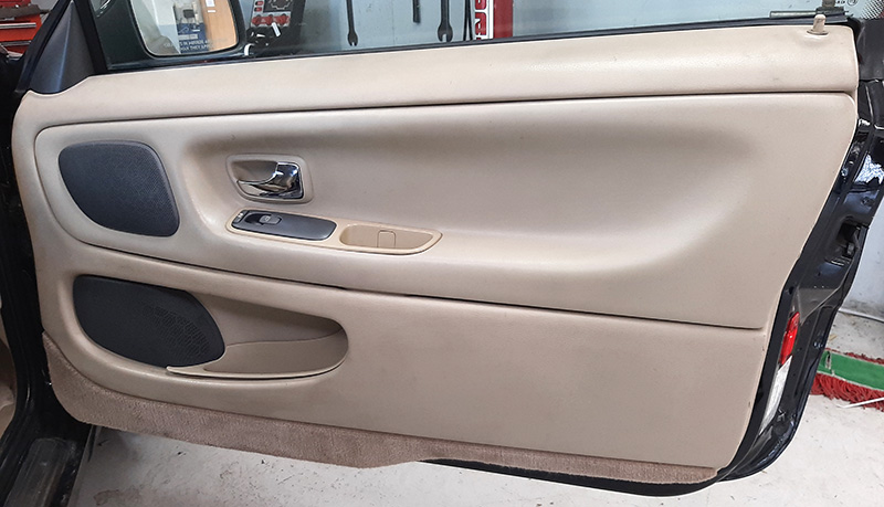
Door panels coming apart
As these cars age, the glue and vinyl in the door panels can crack and shrink.
The door panel is made up of sections that are glued together at the factory. Over time, the glue can fail and the door panel parts can separate.
This does not mean you have to get a new panel or take it to an upholstery shop; in most cases, you can fix it yourself. A hot glue gun can come in handy here.
Removing the door panel
Remove one screw from the handle.
Use a screwdriver with a 10 mm wide tip. Bend the tip to an angle of 90 degrees.
Detach the surround in the order illustrated.
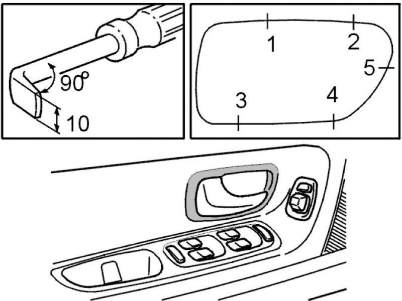
Pry off surround carefully by pressing clips in towards the center of the surround and carefully pulling it outwards using the bent screwdriver.
| NOTE |
|---|
| Protect the door panel. |
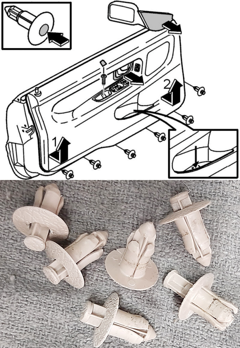
Remove the:
- door mirror panel.
- six press clips at the bottom edge of the door.
- two press clips in the side of the door.
Pull out the bottom edge of the panel.
Lift out the panel. Start at the rear edge of the panel.
The panel is secured using two internal clips at the rear and front edges.
The weatherstrip may come off with the panel on removal. Remove the smaller molding in the weatherstrip.
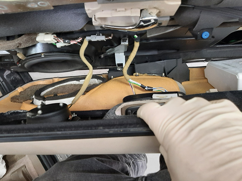
Press the control panel for the power window mechanism upwards by hand from the inside. Disconnect the connectors.
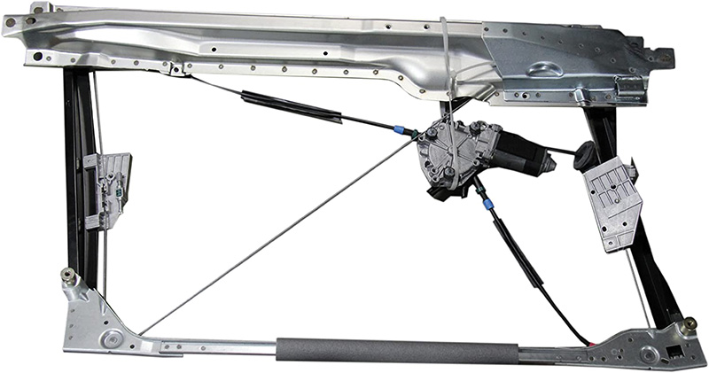
Removing the front power window lift mechanism cassette
| NOTE |
|---|
| Check if the mounting screws have washers between the inner panel and the power window lift mechanism cassette. If this is the case, count the washers. Install the same number of washers for each mounting screw as were removed from between the inner panel and the power window lift mechanism cassette. |
| The window must be up to lift out the cassette. If the window is in the down position, because of a faulty motor or mechanical cable, the mechanical cable directly connected to the motor must be cut off. |
Replacing the lift mechanism motor and mechanical cable for side window
| NOTE |
|---|
| The front adjustment screw must not press into the guide rail. |
Remove:
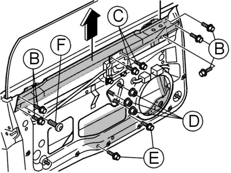
- The connector
- Five screws for the loudspeaker
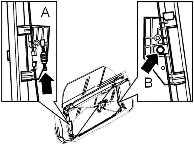
- Four screws (C) for the inner door opener
- The soundproofing mats (Hint: Scrape off the soundproofing mats using a plastic filler spatula.)
- One nut (D) and one screw (E) from the lock bracket
- The connector and the remaining nuts (D) for the lift mechanism motor
- The remaining screw (E) for the SIPS block in the bottom edge of the door
- Lift out the SIPS block
| NOTE |
|---|
| Certain cars between chassis numbers 329 and 604 have standard bolts and washers instead of adjustment screws. Replace with adjustment screws. |
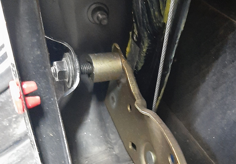
- The lock nuts (A) on both adjustment screws. Counter hold using a Torx screwdriver. Screw in both adjustment screws as far as they will go.
| NOTE |
|---|
| The front adjustment screw must not press into the guide rail. Screw in lightly by hand until it engages. |
- Six screws (B) and (F) in the upper edge of the door securing the cassette in the door.
- Lift out the power window mechanism cassette.
| CAUTION |
|---|
| Take care not to damage the door panels when lifting the cassette out of the door. It is easier if two people lift the cassette. |
Installing the front power window lift mechanism cassette
Lift the power window lift mechanism cassette into place.
| CAUTION |
|---|
| Take care not to damage the door panels when lifting the cassette in. It is easier if two people lift the cassette. |
| NOTE |
|---|
| Turn the motor so that it is in the correct position before lifting in the power window lift mechanism cassette. |
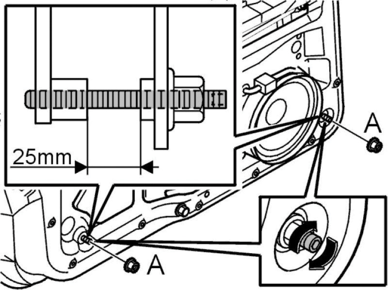
Screw out the adjustment screws so that there is a gap of 25 mm between the power window lift mechanism cassette and the adjustment screw. See the illustration.
Hint: Make a 25 mm spacer, using sheet metal for example, to facilitate measuring between the power window lift mechanism cassette and the adjustment screw.
Install the six screws (B) and (F) for the power window lift mechanism cassette in the upper edge of the door. The door must be closed before the five screws (B) and screw (F) are tightened so that good alignment is retained. Tighten the screws (B). Tighten to 25 Nm. Tighten the screw (F). Tighten to 6 Nm.
| NOTE |
|---|
| The power window lift mechanism cassette is part of the collision protection system. |
Hint: Use a thread sealant to secure the screws.
Install the lock nuts (A) on both adjustment screws. Counter hold using a Torx screwdriver.
Hint: Use a bent wrench.
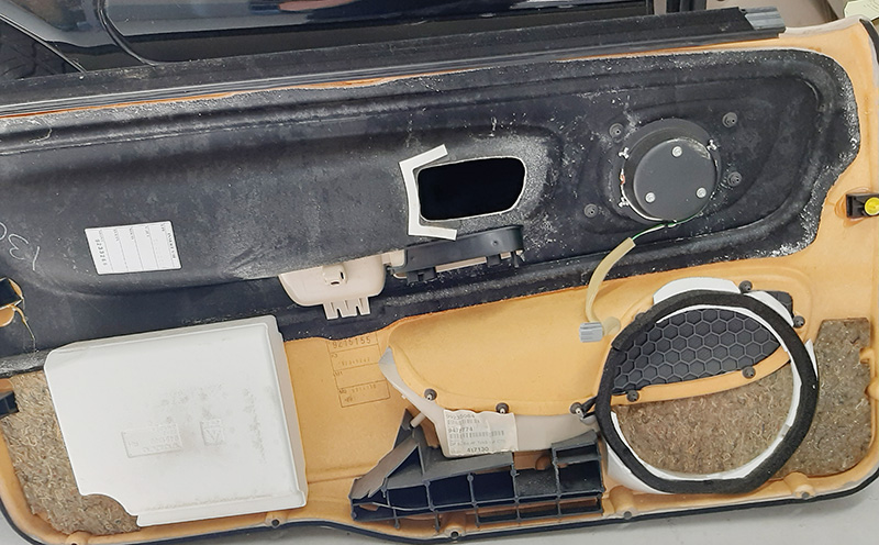
Soundproofing panel
In order for the audio system to retain high sound quality and minimize road noise, it is important that the soundproofing mats in the doors are complete and properly bonded to the doors.
Adjusting the front side window vertically
When the door is shut, two things happen to the window:
- The window is pressed against the weatherstrip.
- Because of its design, the window is pressed upwards.
| CAUTION |
|---|
| The window must be correctly adjusted so that it is not outside the trim strip when the door is closed. |
The door mirror is adjusted last, after adjusting the window to the weatherstrips.
Adjust the upper window position when the cassette is in position in the door. The height can only be adjusted using an adjustment screw on the carriage.
The door panel must be removed before any adjustment can take place.
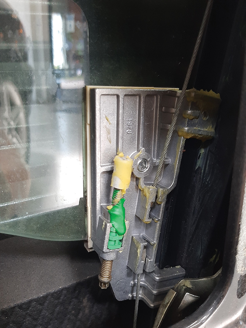
Original position:
- The height adjustment screw must be in the same position as it was when the cables were removed.
- The carriage (B), without an adjustment screw, must not be tightened next to the cable. (Refer to the “C70 window diagram” image.)
Reconnect the motor connector and switch on the ignition.
Run the window up so that the adjustment screw on the carriage (A) is just in contact with the stop at the top of the door.
The front stop must stop 2 mm before the rear stop. If the front stop stops first, the motor continues so that the rear stop reaches the top.
The distance between the rail lower edge and the lower edge of the carriage should be 25 mm greater than the corresponding distance at the other carriage. Replace the lift mechanism motor and mechanical cable for side window.
Mark the cable at the bottom of carriage (B) with a marker pen.
Run the window down a little.
Tighten the screw that locks the carriage (B) to the wire by the mark.
If necessary, adjust the adjustment screw on the carriage (A).
Align the door mirror so that there is a straight line between the door and the door mirror. Check the seal between the door mirror and the weatherstrip. Check for leaks between the window and weatherstrip (see “Checking the seal, front side window”).
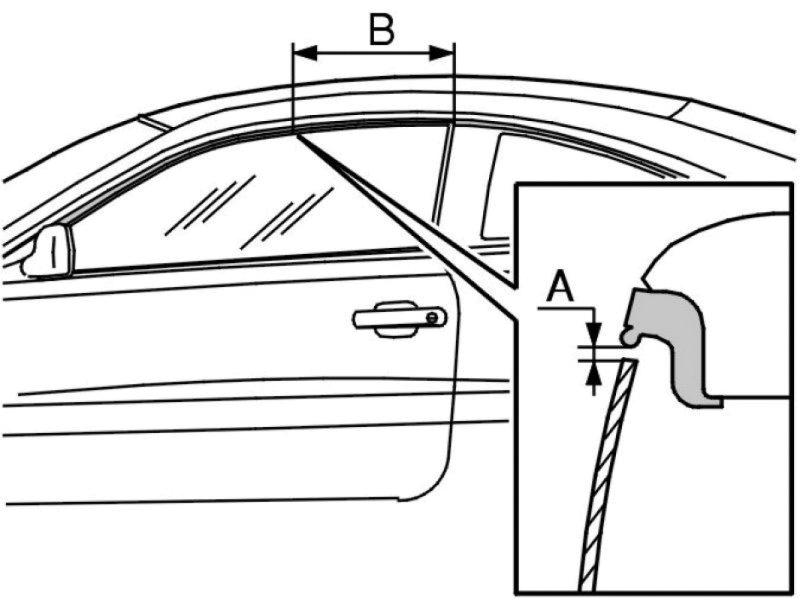
During the closing movement of the door, when the window passes the outer edge of the rubber strip, the distance (A) should be 2-4 mm vertically between the window and molding. Measure 350 mm from the rear edge of the side window (B). These measurements can be seen in the image, “C70 window leak check.”
Adjusting the front side window laterally
The window can be adjusted laterally using two screws in the lower edge of the cassette.
The door panel must be removed before any adjustment can take place (see Components front side door, replacing).
Adjusting the rear side window vertically
The rear side panel must be removed before any adjustment can take place.
The rear side window can be adjusted by moving the stop lug up or down as illustrated.
Check for leaks between the rear side window and weatherstrip.
Adjusting the rear side window laterally
Begin adjusting the window so that it contacts lightly on the corner of the C-post trim and on the weatherstrip on the rear side window. Then adjust the window so that it lies against all the C-post trim, down to the B-post in the same way.
Check for leaks between the rear side window and weatherstrip.
Adjusting the rear side window longitudinally
The rear side panel must be removed before any adjustment can take place.
There is a certain amount of leeway in the mounting of the window in the power window lift mechanism cassette.
There should be 4-6 mm of clearance between the front and rear side windows (B-post) when the door is closed and the windows are completely raised.
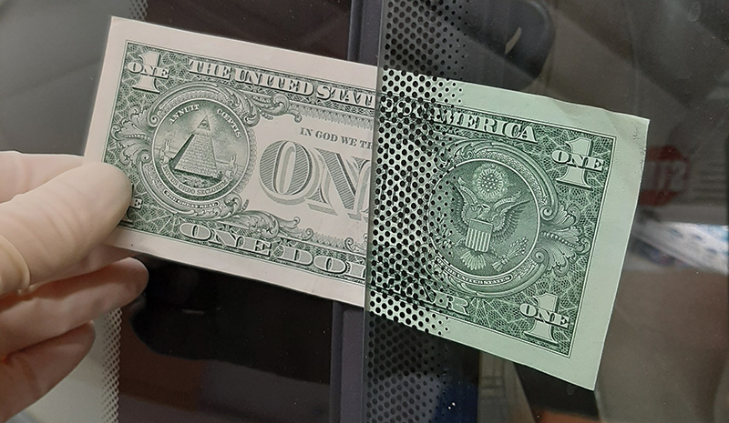
Checking the seal, front side window
Check that the window makes a seal with the weatherstrip around the door opening. Fold a piece of paper in two and pull it out. It should be hard to pull the paper out but not so hard that the paper rips.
The force required should be between 8-22 Nm. Check that the window is in contact with the weatherstrip all the way around the window with the paper.
Spray water over the upper section of the B-post weatherstrip.
Close the door to the first catch point. The door must not be shut completely.
The corner of the window should lie against the B-post trim.
A water bead should form if the window is sealed to the weatherstrip. The water bead should be 20-50 mm long.
The width and shape of the water bead can vary by between 3-6 mm.
If the door is not sufficiently tight, adjust the window.
Spray water over the whole B-post weatherstrip.
Close the door completely.
The rear of the window should lie against the whole of the B-post weatherstrip.
A water bead should form if the window is sealed to the weatherstrip. See the illustration. The water bead should start a maximum 10 mm under the upper edge of the window and all the way down the B-post. The width and shape of the water bead can vary by between 3-10 mm.
If the door is not sufficiently tight, adjust the window. Repeat the vertical and side to side adjustment until the window is correctly positioned against the weatherstrip.
When the window is in the correct position, lock the adjustment screws with the lock nuts at the lower edge of the power window lift mechanism cassette.
Adjusting doors
The doors must be easy to open and close.
The edges of the door must be flush with the car exterior.
The front edge of the door must be 0-1.5 mm inside the front fender, and the rear edge of the door should 0-1.5 mm outside the bodywork.
The door length can be adjusted by installing or removing shims on the upper and lower hinges.
0.3 and 0.5 mm shims are available as replacement parts.
Adjusting the striker plate
Check to see if the striker plate and latch pin have excessive wear before you attempt to adjust the striker plate. If the parts are too worn, it may be time to replace them.
A striker plate or latch pin that is too worn may not be able to be adjusted enough to ensure reliable door latch operation.
The door must not rest on the striker plate. The striker plate must not press the door upwards.
There are rectangular holes in the striker plate. Slacken off the striker plate screws just enough to allow the striker plate to be moved stiffly.
Hold the handle out while closing and opening the door. Repeat until the striker plate is correctly adjusted.
Then tighten the striker plate screws.
Check the function of the lock by opening and closing the door.
Adjusting the travel of the external door handle
Insert the key into the lock and turn it so that the lock rod is out of the way of the screwdriver.
Adjust using a Phillips screwdriver.
Hint: If it is incorrectly adjusted, it may not be possible to open the door from outside.
Yes, these cars are becoming rarer every year. But, if you have the opportunity to work on one of these unique Volvos, you should read up on them before performing any repairs on the doors or windows.


0 Comments