
In this article we’ll cover the components that make up Toyota inverters, how they work, and some failures you might see in your shop.
Inverters solve a fundamental problem with using a battery to power a vehicle. The problem? The best Motor/Generators (MGs) work with alternating current (AC), but a battery pack can only store direct current (DC). An inverter solves this issue by converting AC to DC and vice versa, which allows the battery to power the MGs and thus allows the MGs to charge the battery. Toyota inverters also have several other functions, such as increasing MG efficiency, charging the 12 volt battery, and running the electric air conditioning compressor.
In this article, we’ll cover the components that make up Toyota inverters, how they work, and some failures you might see in your shop.
What’s in the Box?
IPMs
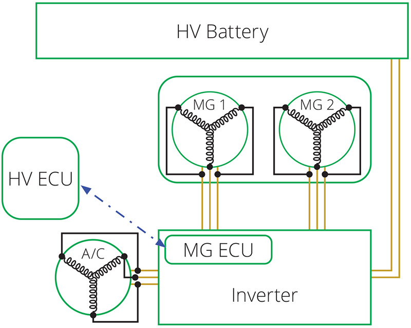
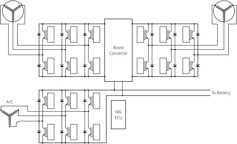
The Intelligent Power Modules (IPMs) are a set of six transistors and drivers that control current flow through the MG windings. The IPMs convert DC power from the battery to waveforms that will drive the MGs at the desired torque and speed while the MGs are working as motors. When the MGs are running as generators, the IPMs convert their AC voltage output to DC to charge the battery.
Boost Converter
Another function is increasing voltage levels using a step-up (boost) converter. An electric motor runs more efficiently at higher voltages. A motor’s windings are just long pieces of wire after all, so voltage drop is an issue. For any given power (volts x amps), voltage drop on a length of wire will be lower with higher voltage and lower amperage. Using a DC-DC boost converter, the inverter increases the battery pack voltage before it’s converted to AC.
The boost converter consists of a coil of wire (inductor) that’s rapidly cycled on and off by a pair of transistors, which Toyota calls the “IPM for boosting.” When the IPM is on, current flows through the inductor and it generates a magnetic field. When the IPM turns off, the magnetic field collapses, creating a voltage spike higher than the original voltage applied. The voltage spike flows through a diode to a capacitor for storage and smoothing. The MG ECU adjusts output voltage by adjusting inductor on-time.
Two key data PIDs for the boost converter are VL (Voltage Low) and VH (Voltage High). VL is the inverter voltage before boosting and VH is the voltage after boosting. VL should be nearly the same as the battery pack voltage PID “Power Resource VB” (Voltage Battery), since they are measured on opposite sides of the DC cables that go from the battery pack to the inverter. If the voltages aren’t the same, a trouble code P3004 will set.
| 346-Power Resource VB | 236 | V |
| 346-Power Resource IB | -22 | A |
| 346-Shift Sensor Shift Pos | D | |
| 346-Accel Sensor Main | 33.3 | % |
| 346-Auxiliary Batt Voltage | 13.79 | V |
| 346-Converter Temperature | 176 | F |
| 346-VL-VL-Voltage before boosting | 234 | V |
| 346-VH-Voltage after boosting | 498 | V |
DC-DC converter
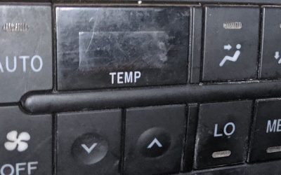
The inverter also powers the car’s 12 volt systems and charges the 12 volt battery, replacing the alternator on a traditional gasoline-only car. Another DC-DC converter handles this task. It’s a step-down (buck) converter that typically lowers the battery pack voltage to 13.5 or 14V.
Usually, when Toyota says “DC-DC converter,” they’re talking about this one. However, the boost converter is also a DC-DC converter, so some code descriptions will say DC-DC converter when they mean boost converter. For instance, codes P0A08, P0A09, and P0A10 set when a 12V DC-DC converter fault is detected. However, a code P0A94 “DC-DC converter performance” indicates a fault with the boost converter, not the 12V DC-DC converter.
A/C Inverter
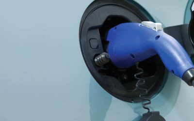
Finally, the inverter drives the motor in the electric A/C compressor on some models. Other models have an additional inverter built into the compressor itself. You can tell which style is fitted by looking at the orange wires connected to the compressor. Two wires mean the A/C compressor has an integral inverter. Three wires mean the AC inverter is in the main inverter housing.
The A/C driver is similar to the IPMs and is comprised of a set of six transistors, six diodes, and a control circuit.
Measurement and Control
The inverter has some processing power, but you won’t find it listed as a control unit on the LAN chart, and the data it generates is usually displayed in the Hybrid ECU (or Power Management ECU) data list.
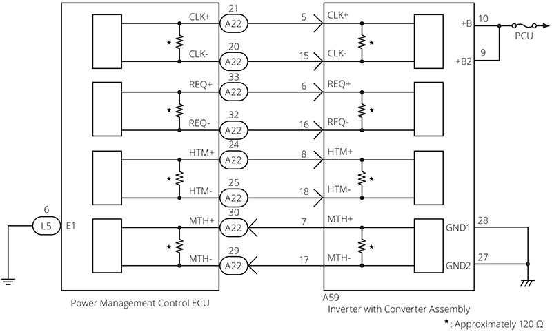
Voltage and current measurements from sensors inside of the converter are processed and sent via dedicated communication lines that connect the inverter with the HV ECU. The inverter has built-in diagnostic logic and can set trouble codes on its own, and then relay the trouble code to the Hybrid ECU.
Current Sensors
The current flowing in or out of each of the MGs is monitored by the MG ECU and this data is sent to the Hybrid ECU. Since the MGs are Wye wound and are not center tapped, any current flowing into one phase must flow out of one of the others. Therefore, only two phases of each MG have current sensors. The Hybrid ECU uses data from the current sensors in the inverter to check the performance of the current sensor in the battery pack.
Capacitor Discharge
Capacitors can store voltage indefinitely. The capacitors in the inverter are charged to dangerous voltage levels, so it’s important that they are discharged every time the car is turned off to prevent injury during service work.
Toyota does this in two ways: active discharge and passive discharge. Active discharge should occur when you turn the car off. An IPM shorts the capacitors through an MG winding, bringing the capacitor voltage close to 0V. But what if the car is broken and this doesn’t happen?
That’s where passive discharge comes in. There’s a resistor wired in parallel with the capacitors. If active discharge doesn’t work properly, the resistor will drain the capacitors, but it will take some time. This is the reason for the “wait 10 minutes before opening the inverter” warning. It shouldn’t be necessary if active discharge works, but if it doesn’t, waiting might save your bacon.
| HINT: |
| Waiting for at least 10 minutes is required to discharge the high-voltage capacitor inside the inverter with converter assembly. |
Inverter Cooling System
Unfortunately, none of the inverter’s electrical components are 100% efficient, and the losses are converted to heat. Since the inverter handles a lot of power, it also generates a lot of heat. To prevent components from getting too hot, Toyota uses a separate cooling system for the inverter electronics. This consists of liquid cooled heat sinks, passages and hoses, a dedicated radiator, and an electric pump to keep coolant circulating through the system.
Unlike a cooling system used for an Internal Combustion Engine (ICE), the inverter doesn’t need to “warm up” to operate efficiently. Therefore, there’s no thermostat. Earlier systems ran the coolant pump whenever the car was on. Newer systems turn the pump on as needed based on the inverter temperature, which is measured with sensors in both IPMs. You can use a Techstream active test to command the inverter pump on for testing in later systems.
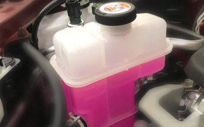
Since the ICE coolant runs around 190 degrees F, which is way too hot for the inverter, the inverter and ICE never share a cooling system. On some models, it may look like there’s a common radiator for both the ICE and the inverter, but the coolant passages are separate for each system, and you’ll notice separate inlet and outlet hoses for the inverter and the ICE.
Interlock System
There are dangerous voltage levels in the inverter. You certainly wouldn’t want to try to perform any repairs while the system is live. All hybrid repairs should begin with “safing” the system by removing the service plug with the car off and 12V battery disconnected.
These three steps will help keep you safe while working on the car: Turning the car off will open the System Main Relays (SMRs), removing battery voltage from the inverter. Disconnecting the 12V battery will prevent SMR activation. Removing the service plug will split the battery and break the connection between the positive and negative high voltage cables, and it will also break the interlock circuit to prevent accidental activation.
What if someone ignores the safety rules and decides to remove the inverter cover with the car Ready? Toyota considered this possibility and created safeguards. The interlock system runs through jumpers attached to the inverter cover. If the inverter cover is removed, the interlock circuit is broken and the HV control unit will open the system main relays and discharge the capacitors in the inverter. However, you should always follow the procedures outlined in TIS. Safety is achieved through redundancy.
Common Problems
DC-DC Converter Overheating
One relatively common issue is caused by problems with the inverter cooling systems. If the inverter temperature climbs too high, the DC-DC converter will shut down to protect the inverter. This will produce symptoms very similar to a failed alternator. First, warning lights appear. Then, if the driver keeps on driving, the 12V battery State Of Charge (SOC) will drop and the car will eventually stall. Customers may report flickering displays and other electronic malfunctions before the car stops altogether.
Assuming you still have freeze frame data (it can be lost due to low 12V battery voltage), you’ll likely find a code P0A93 (inverter cooling system performance). There are two sub-codes associated with P0A93 – 346 and 347. An inf code 346 indicates a problem with coolant flow and can be caused by a bad pump or blockage in the cooling system. An inf code 347 sets when both the inverter coolant temperature and the ICE coolant temperature have both risen, and usually indicates a problem with the air flow over the radiator.
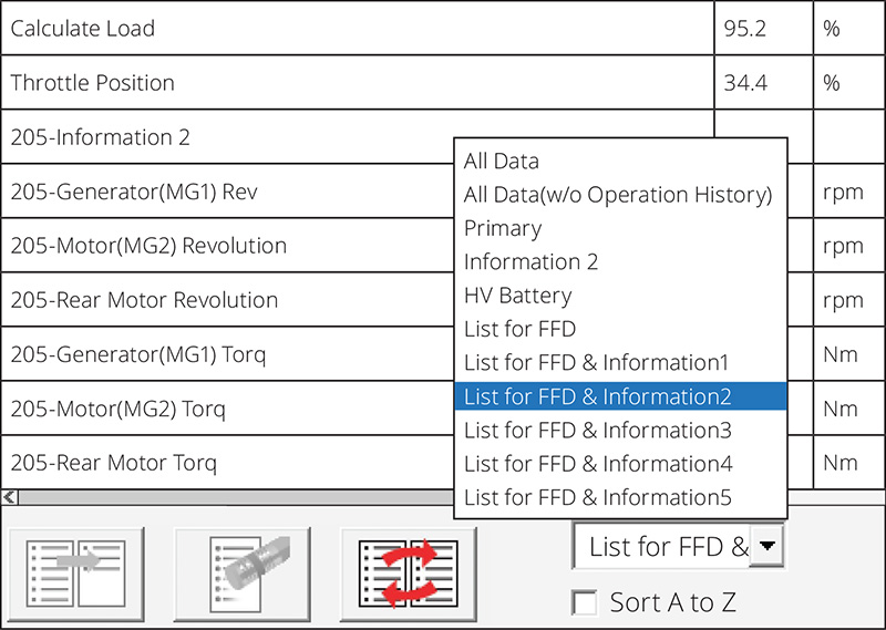
When using the Techstream, remember that there is usually more freeze frame data available when you select the appropriate “information section” in the drop down (see picture). The freeze frame data will usually show high temperatures for the “MG1 inverter” and “MG2 inverter.” What’s too high? Anything over 160 degrees F is abnormal and usually it stays much lower than that.
DC-DC Converter Failure
DC-DC converter failure is extremely uncommon, unless…
Jump starting a car seems pretty simple to you and I, but the same isn’t true for everyone. Even if you know nothing, you’ve got a 50/50 chance of getting it right. Unfortunately, many drivers lose that coin toss. Connecting jumper cables backwards will blow the main fuse for sure, and sometimes it will damage the DC-DC converter as well. Many inverter components, including the DC-DC converter, are available from Toyota dealerships. You can save your customers thousands by doing a little research and repairing inverters rather than replacing the entire unit.
IPM Failure
Some of the Gen3 Priuses and Gen1 Highlanders had IPM failures. The most important thing when diagnosing a suspected inverter fault is careful reading. Toyota has updated the information on TIS to reflect changes in diagnostic procedure and parts recommendations. If you take the time to read the information available in TSBs and the service manual, things will work out fine. On the other hand, quickly skimming can lead to replacing good parts unnecessarily, replacing the wrong parts, or damaging the inverter during the repair.
Isolation Faults
All high voltage systems are isolated from chassis ground on hybrid and electric vehicles. As mechanics we’re very used to thinking of electrical systems as being chassis grounded, since that’s how nearly all 12V systems are designed, so it can be hard to absorb this concept at first. However, high voltage systems should never be electrically tied to the chassis.
High voltage isolation is continuously tested, and if a connection between high voltage and the chassis is detected, a fault code will set — P3009 on older hybrids and P0AA6 on newer hybrids. The newer hybrids also set an information code to indicate the location of the leak. If the leak is in the inverter, a P0AA6-614 will set.
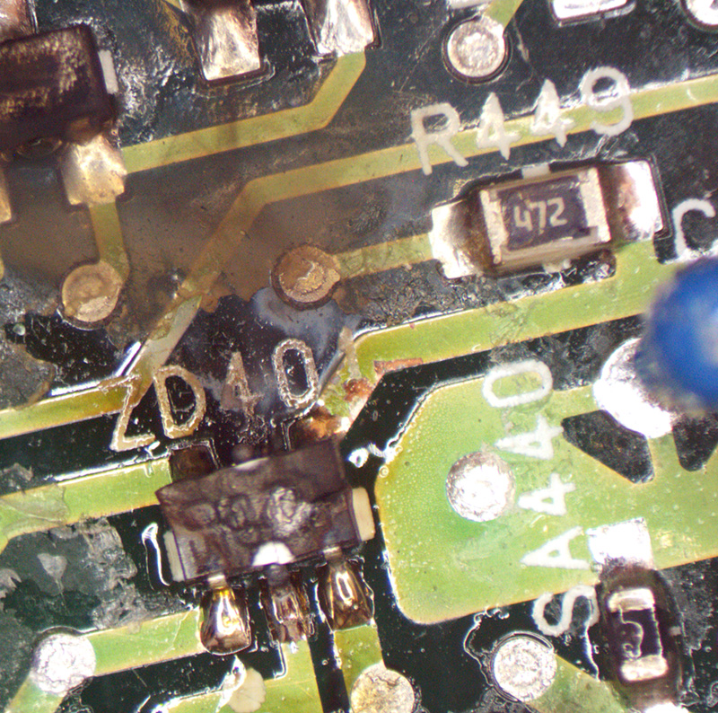
Inverter isolation faults rarely occur on their own. However, Toyota inverters are located in the front of the vehicle and can be damaged in a collision. A cracked inverter case can cause coolant intrusion, and coolant in areas where high voltage is present can cause isolation faults. Also, air conditioning connectors and cables can be damaged in collisions as well, since all high voltage cables are shielded to reduce radio frequency interference and for fault detection. Finally, sloppy repair work can introduce conductive debris into the inverter and cause isolation faults.
Like Any Other Automotive System
Hopefully, this overview was enough help you feel comfortable diagnosing and repairing inverters, if you weren’t already. As always, TIS will have all the service bulletins, tech tips, diagrams, and repair information you’ll need for successful repairs, so be sure to start there.
By Paul Cortes
0 Comments