These days, when we see a wheel speed sensor code can we really afford to just throw a new sensor at it? For most GM vehicles, that means a whole wheel bearing assembly. With parts and labor being what they are, we’d better make sure.
“If you had asked me at the beginning how this repair was going to end, I never would have guessed right.” Yes, we often make general assumptions that a problem could be due to component failure, a wiring issue, or maybe software. But most of the time we believe down deep that replacing a component will take care of things even though in this day and age we should know this is not always the case. For the most part when we see a warning light (or, in this case a few warning lights) we reach for our scan tool. A good move considering that the self-diagnostic system has reported a problem and our scan tool can retrieve that information. We also know it is not going to tell us what is wrong, unless it is a catastrophic failure that could just as well be identified by a simple visual inspection. But in the very beginning of a diagnosis, how do we know if the problem is deeper?
The Truth
The truth is we never do. We’re sure most of you have the good sense to road-test the vehicle thoroughly before it is delivered to the customer. But how much time can you invest in this? In this economy, customers are tightening their belts, so unless you’re in some kind of niche market you have to work harder for every dollar you earn. This may lead to shortcuts, and in the end this one cost us. We were lucky the customer was understanding and realized the problem was difficult to see on this 2002 Cadillac Seville SLS.
The car came in with the ABS and brake light on, and a warning message in the driver’s information center of the instrument cluster. It reported that the ABS and Traction control System (TCS) were no longer working. We found a code C1227 Left Rear Excessive Wheel Speed Variation. We also retrieved a U1000 code Class 2 Data Link Malfunction, but after recording failure records we cleared the codes and the U1000 did not return. So, we put that one on the back burner to see if it would resurface later.
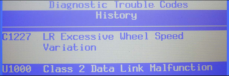
After a short road test the C1227 did return. During the drive we looked at the indicated wheel speeds with our scan tool data and everything appeared to be fine. There did not appear to be any difference between the left rear speed and that of any other wheel, let alone the right rear. A quick look at the tires indicated they were all of the correct size and were all the same model. In extreme cases, you may need to look at tire wear. A brand new tire can have a significantly larger circumference than a worn one. Remember, customers may be replacing these tires one at a time these days. ABS units can pick up on this small variation in wheel speed, but this was not the case here. Even though the problem was not evident yet, we were already starting to think wheel bearing/sensor assembly.
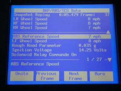
We knew it was possible that the signal was dropping out faster than the scan tool’s display could catch it. It was also possible the signal was getting weaker as the bearing was put under load in turns, which can increase the air gap between the tone wheel and the sensor pickup. We couldn’t inspect any of this since it is incorporated in the sealed wheel bearing assembly. We usually ask for one hour of diagnostic time, particularly if the problem is intermittent. Although the code came back during a road test, it still appeared okay while watching the data. Well, this customer was going to get his money’s worth. We put a vehicle on the lift and checked the sensor connections. Everything looked good. Took a quick look at wheel bearing play. It didn’t seem particularly bad, but this vehicle did have 100,000 miles on it. Are you reading what we’re trying to convince ourselves of? After the work, we road tested it and no code reappeared. That was easy.
A few days later the vehicle was back in. We spoke with the customer, who happens to be a nice guy. He said it took a few days, but the warning lights did come back on. He understood it may be something else and left us with the vehicle for a few days. I immediately pulled codes and there it was C1227 all by itself. Another road test and everything is the same. Almost no variation in wheel speeds. Keep in mind it is normal for the front wheel speeds to vary by a few miles per hour in turns. The wheels are actually traveling at two different speeds, so don’t be fooled by that. These are also the rear wheels we are flagging codes for. After taking a look at the failure records available with a Tech II scan tool, we found that the problem was occurring at very low speed — under 5 mph!
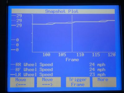
Depending on you aftermarket scan tool, you may or may not be able to see failure records. That’s okay; you just may have to be more thorough with your testing. During our road test we were traveling at normal road speeds, but the problem occurred at very low speeds. We were monitoring the wrong situation. We decided to perform a low speed road test and see if we could see the problem. Another feature of the Tech II is that you can graph plot the data that you have recorded in a snapshot (on most scan tools you can graph data and possibly see the wheel speed variation at low speed). The graph did show the variation in wheel speed below 5 mph. The difference was only one to two miles per hour. We have seen this before on scan tools and it never flagged a code. Where else could we look?
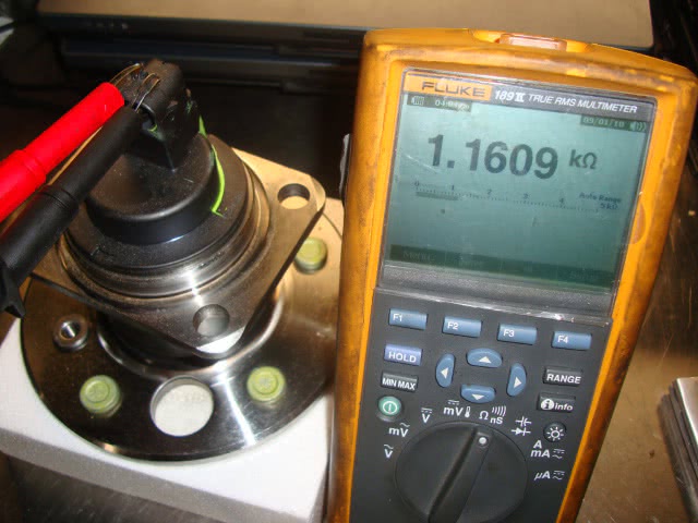
Maybe we had a bad replacement part. It was not OEM and we hear there are a lot of cheap parts being made in developing countries that make their way to our parts shelves. We were going to have to diagnose this problem all over again. We went back and checked the resistance of both sensors. The new replacement sensor read 1,300 ohms, whereas the old sensor on the other side measured 1,100 ohms. Was this enough to generate a difference in the AC voltage pattern? We decided to check the AC voltage coming off the wheel speed sensors while spinning the wheels by hand. With each wheel, we were able to generate .5 of a volt and both were pretty even. These measurements were taken at the sensor itself, so the wiring leading to the control unit wasn’t taken into account. What were we going to have to do to check that?
On this Seville the EBCM is mounted underneath the hood, towards the front inner sub-frame — not an easy place to get to. If you remove the air filter for the secondary air pump you can access the control unit connector. Pull out the locking tab on top and rotate the connector tab to the unlocked position and you should be able to pull down the connector. Looking at a wiring diagram, the left rear signal line is pin #22, a black wire. Pin #8 is a red wire and it is the ground. Here we were able to measure the same 1,300 ohms we measured at the sensor. Pins #9, brown, and #23, white, are the signal and ground respectively for the right rear sensor. Here we measured the same 1,100 ohms. So, wiring appears not to be a problem, at least at the moment. Where to look next?
As a matter of course, I typically clean any control unit connector that I unplug. There are any number of suitable solvents available through your local parts supplier. In this case, it just so happened I had my Stabiliant-22 bottle within easy reach. Being expensive stuff, I only used four drops on the four pins for the rear speed sensors. I then prepared for the arduous task of connecting my scope leads and running them safely into the cabin so I could watch the signals I was about to scope. I needed to see the signals during the problem. This may sound simple, but the reality is that it’s fairly difficult. We have to scope the signals while driving and therefore keeping the wheel speeds even. To run scope leads from either the rear sensors or the EBCM is a time-consuming task. Finally, we got to drive.
While looking at the scope signals during the drive (with someone else driving, of course — this is for the lawyers), we noticed a slight difference in the amplitude of the voltage signal. The right rear was putting out just under one full volt, but the left rear was putting out just over one volt, maybe 1.25 volts. Remember that the resistance values were slightly different and therefore the AC voltage signals could be slightly different. We were stumped at this point, so we started thinking outside the box.
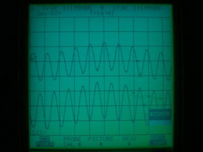
We once had a Honda where the ABS sensor wire was routed close to the alternator output wire. When the alternator started to charge it would flag a left front wheel speed code. We were hoping that we did not have to look for a problem like that, but as luck would have it we no longer had a DTC for the left rear sensor and all the warning lights stayed off.
Cleaning the connector at the EBCM and adding the Stabiliant-22 corrected the electrical connection of the left rear wheel speed sensor. If we hadn’t followed our habit of cleaning pins and applying electrical contact enhancer whenever we unplug a connector, the problem would still not have been fixed. Now, we may have actually had a bad bearing. The problem did take a few days to come back. It had seemed like a straight-forward repair at the time.
Our lesson learned here is to check and clean all electrical connections involved with the code. In this case, that would be the pins in the EBCM connector and the sensor itself. If there had been a connection in the harness we would have cleaned that one as well. This may be slightly more time consuming, but if you include the time in the initial estimate the customer may pay for the additional labor. If the car comes back for the same problem it is a harder sell. In the end, we had to eat the additional hour spent on this diagnosis but at least the problem was dealt with and we maintained our good relationship with our customer. In the end, that’s all you could ask for.
by Kerry Jonsson


0 Comments