This article provides information about the Subaru Legacy fuel injection and engine management systems.
This article provides information about the Subaru Legacy fuel injection and engine management systems. The fuel injection and engine management systems on other Subaru models, while similar to the Legacy systems, contain key differences that will be addressed in a future End Wrench.
Air Induction System
The air induction system provides the correct amounts of air to the cylinders under a variety of operating conditions and performance demands. Components include:
- Air Induction Piping
- Mass Air Flow Meter
- Throttle Body
- Idle Air Control Valve
The air induction piping delivers air from the air filter to the throttle body, idle air control valve and the PCV system. Fittings to the components of the air induction system must be air-tight to prevent unmetered air from entering the intake manifold.
Mass Air Flow Meter
Monitoring the amount of air inducted is the main function of the mass air flow meter. Described as a “hot wire†air flow meter containing no moving parts, the Subaru mass air flow meter obtains information by monitoring the voltage of a single wire which is exposed to the incoming air flow. There are actually two wires exposed to the air flow. The hot wire is positioned downstream of the cold wire to prevent any influence to the cold wire. The engine control module (ECM) logic monitors the temperature of both wires using stored information about their resistance values and the voltage in the wire. The ECM attempts to maintain a fixed difference in the temperature of these two wires. The amount of voltage applied to the hot wire is what finally determines the value of the signal generated or “Air Quotient.â€
Air Quotient (QA), is one of the input signals to the ECM that determines the amount or length of time that fuel is injected. Two other inputs are the throttle position signal, generated by the throttle position switch (TPS) and engine speed (EREV), which is a processed signal determined by the ECM based on input from the crank and cam angle sensors.
Fail-Safe
Fail-safe, the action taken by the ECM in the event a component is not operating within established parameters, forces the ECM to determine injection duration using TPS and EREV only.
Mass Air Flow Sensor Circuit Testing
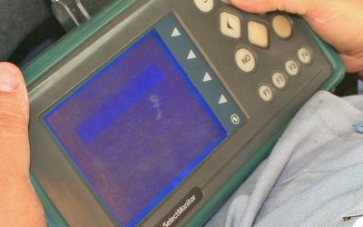
Testing is performed by observing resistance and voltage values. The QA value can be monitored using the Select Monitor. The QA value should increase with engine speed and decrease to approximately 1 volt as engine speed approaches idle. A fail-safe value will result in a constant signal which is not affected by engine speed.
Replacement Parts
The installation of improper replacement parts will result in a driveability or no start condition. Verify with your parts department using Vehicle Identification and Production Date numbers as necessary. For example, early production Legacy vehicles were equipped with either a JECS or HITACHI produced air flow meter, depending on whether they were automatic or standard shift transmission vehicles.
Throttle Body
The throttle body regulates the amount of air into the intake manifold, controlling off idle engine speed. Operation of the throttle body is accomplished by movement of the accelerator cable. Coolant flows through the base of the throttle body to prevent ice from forming. The throttle body is factory set and no adjustment should be attempted to the throttle plate. Adjustment of the throttle cable is suggested during periodic vehicle maintenance.
Throttle Position Switch
The throttle position switch (TPS) is mounted to the throttle body and engages the throttle shaft. Any movement of the throttle shaft results in the movement of a contact across a potentiometer. At idle the throttle position switch resistance value is high, so the voltage signal at the moveable contact is low. As the throttle is depressed, the resistance value decreases and the voltage at the moveable contact increases. The voltage signal, which ranges from 0.3 to 5 volts, is used by the ECM to determine the position of the throttle expressed in degrees of opening.
Some Legacy models were equipped with a TPS with an inverted voltage signal. Voltage was approximately 5 volts at idle and decreased as the throttle was depressed.
An idle switch is also included inside the TPS. The idle switch signals idle and off idle to the ECM. Adjustment of the TPS is possible through the use of its elongated mounting holes.
Fail-safe operation results in a fixed TPS voltage signal while the ECM uses the idle switch, QA and EREV to control injection duration.
Testing of the TPS is performed by observing voltage and resistance values. The Select Monitor on earlier models will display THV or throttle voltage and illuminate an LED when the idle switch signal is present. Newer models will also indicate throttle opening in degrees.
Idle Air Control Valve
Idle Air Control Valve (IAC) operation controls all idle speeds. Construction includes an air cut valve, duty control valve, intake air passage and a coolant passage. These component parts create a dual control over the IAC. The air cut valve is influenced by the temperature of coolant flowing through the IAC. A bimetallic spring is utilized to act on the air cut valve, opening the valve when coolant temperature is low to increase air flow and idle speed. When coolant temperature is high, the bimetallic spring closes the air cut valve and decreases airflow and idle speed.
Duty control valve operation is achieved via two electrical coils, one to open the valve and the other to close it. The ECM controls the ground circuits of the two coils and controls them with a duty signal which pulses the ground circuits.
IAC duty ratio can be monitored with the Select Monitor. A higher duty ratio will keep the valve open longer, increasing idle speed. A lower duty ratio provides lower idle speeds. Optimum idle speed for all engine conditions is part of the ECM logic and the ECM will increase or decrease the IAC duty ratio as necessary to maintain the correct idle speed.
Fail-safe results of the IAC can be misleading. Failure of the bimetallic spring with the air cut valve in the more open position will not cause a problem when the engine is cold. But as the engine warms the duty ratio of the IAC will be lower than normal to close the duty control valve more to maintain proper idle speed. Failure of the bimetallic spring in the more closed position will result in higher IAC duty ratio with a cold engine but will be normal with a warm engine.
Failure of the duty control valve or loss of duty signal will leave the duty control valve fully open. With a cold engine, the air cut valve is also fully open. This quantity of air flowing through the intake air passage would result in an improper high idle speed. To control this condition, the ECM turns off injectors to reduce idle speed. One injector will be disabled for a warm engine and two injectors for a cold engine.
The intake air passage can be contaminated with carbon, which reduces the air flow. This condition would result in a higher than normal IAC duty ratio. If this condition is suspected, clean the IAC valve following procedures outline in the service manual.
Fuel Supply
The fuel supply system supplies, regulates and monitors the flow of gasoline to the injectors. Components include:
- Fuel Tank
- Pump
- Rollover valve
- Separator
- Regulator
- Injectors
The fuel tank houses the fuel pump and a jet pump on AWD models. Interference with the rear differential is avoided by shaping the tank in a saddle design. This design makes it necessary to supply a means of shifting fuel from one side of the tank to the other. The fuel pump is on the right side of the tank as viewed from the rear, with the jet pump pickup is on the left. The speed of the fuel returning to the tank is used by the jet pump to create a siphoning effect, transferring fuel from the left side of the tank to the right. The main fuel pump can then pick up the fuel.
The fuel sending units, one on each side of the tank, are wired in series to provide the fuel gauge with correct information to show correct fuel level.
The fuel pump creates pressure by moving the fuel through a series of impeller vanes and centrifugal force. Pressurized fuel flows through the clearance between the armature and the magnet of the motor to the discharge port of the pump. If the pressure output is too high a relief valve opens and the pressurized fuel exits the pump to the tank. When the pressure returns to normal, the relief valve will close.
Fuel Pressure Regulator
The fuel pressure regulator uses spring tension and manifold pressure to controls fuel pressure. Pressure is controlled by adjusting the size of a passage, which limits the amount of pressurized fuel that is allowed to return to the tank. When manifold pressure is high during acceleration the opening is small, and less fuel is allowed to return to the tank. This provides higher fuel pressure at the injectors. During conditions of low manifold pressure, the opening is large and more fuel returns to the tank, reducing the fuel pressure at the injectors. A check valve in the regulator maintains pressure in the fuel system after the engine is turned off.
Caution: The fuel system is always under pressure. Disconnect the fuel pump and start the engine to remove the pressure. Allow the engine to run until it stalls and attempt to restart. Turn the key off. The system is now safe to open. Follow all safety procedures outlined in the appropriate Subaru service manual.
Fuel Injector
The fuel injector, which delivers fuel to the intake manifold, is described as a galley or side-feed type.
The ECM controls the injectors by varying the ground signal. A magnetic field develops inside the injector when the ground is established. The magnetic field lifts a plunger off its seat and fuel under pressure enters the injector and exits through the tip of the injector. The design of the tip creates the proper spray pattern for the best mixing with air in the manifold.
The time or length of grounding of the injector circuit is referred to as injection duration. The select monitor will display injection duration as “TIM†(Injection Duration).
Crank Angle Sensor
Crank angle sensor operation determines crankshaft position and speed by sensing pulses created by a reluctor passing through a magnetic field. The reluctor is machined to the back side of the crankshaft timing belt sprocket. The shape of the reluctor teeth is very important to the strength and clarity of the signal produced. A chip or deformation on any tooth can result in a driveability or no-start condition. The signal generated is A/C and varies from approximately .5 to 1.5 volts.
The crank angle sensor contains a permanent magnet and a coil of wire. Do not drop the crank angle sensor as the magnet or the shape of the sensor may be damaged, which can alter the signal generated.
The crank angle sensor reluctor has six teeth arranged in pairs of two. The teeth are set at 10, 65 and 97 degrees BTDC.
The ECM uses the crank angle sensor input to influence or control the fuel and ignition systems. (Determines engine rpm, fuel injection timing, dwell and timing advance.)
Cam Angle Sensor
The cam angle sensor functions in the same manner as the crank angle sensor. However, the value of the cam angle sensor A/C signal is slightly lower and the signal pattern is different. Cam angle sensor reluctor teeth are located on the back side of the left camshaft sprocket. The ECM uses the cam angle sensor to determine fuel injection sequence and to reference the #1 cylinder.
Fuel Injection Logic
The amount of fuel injected or duration is determined by the following:
Basic Duration + Correction Factors + Voltage Correction
Basic duration is determined by comparing QA and engine speed. Correction factors include:
- Start increment
- Coolant temperature
- After start
- Full increment
- Acceleration
- Air, fuel coefficient
Voltage correction compensates for the injectors time lag affected by battery voltage.
Learning Control
The amount of air monitored by the mass air flow meter or QA compared to the engine rpm is memorized by the ECM. This results in a representation of engine load. Engine load is used to update basic duration.
Ignition System Control
The distributorless (direct ignition) system uses the crank and cam angle sensor inputs processed by the ECM to control ignition and ignition timing. This system uses a coil pack that houses two coils to separately supply secondary voltage to two cylinders.
Cylinders:
Forward coil    #1 & #2
Rear coil #3 & #4
The secondary voltage is sent to the spark plugs of two cylinders simultaneously. One cylinder is on the power stroke and the other is on the exhaust stroke.
Caution: During cylinder power balance tests, do not allow fuel to enter the exhaust system. Always disconnect the appropriate fuel injector harness, do not short secondary voltage to the cylinder. Shorting the secondary voltage will allow fuel to enter the cylinder. The spark plug may fire on the exhaust stroke when ignition is restored. This may cause severe damage to the exhaust system. Never start the engine with the exhaust removed, as the cylinder firing on exhaust stroke may ignite unburned fuel.
Igniter
The coils are controlled by the igniter. Igniter construction is composed of two transistors that control the ground circuits of the primary windings of the coils. Transistors in the ECM control the igniter. The igniter is necessary because of the amperage flow through the primary windings would damage the ECM.
Signals from the cam and crank angle sensors are received by the ECM. At engine start the ignition timing is fixed at 10 degrees BTDC. After engine start, ignition timing is influenced by the mass air flow meter, coolant temperature, knock sensor and engine load.
Engine knock is detected by the Knock Sensor. The sensor contains a piezo electric element that generates a small A/C voltage signal
when a vibration at the correct frequency is present on the engine block surface. The signal that is created is used by the ECM to influence ignition timing.
Self Diagnosis System
Self diagnosis has four modes:
- U-Check – monitors components necessary for start up. The Check Engine Light will be illuminated during normal vehicle operation when a problem is detected.
- Read Memory – Used to read past trouble codes. Activated by using the black connectors located under the driver side kick panel, and following the procedures outlined in the service manual.
- D-Check – Used to check the present condition of all MPFI components. Activated by using the green connectors located under the driver side kick panel, and following the procedures outlined in the service manual.
- Clear Memory – Clears all codes in ECM memory. Activated by using the green and black connectors located under the driver side kick panel, and following the procedures outlined in the service manual.
In both D-Check and Read Memory modes, the control unit outputs trouble codes by using the Check Engine Light. Long flashes equal 10 and short flashes equal 1. By adding together the numerical equivalent of the flashes, you can identify the correct trouble codes. Multiple trouble codes are outputted in chronological order. You will find a list of trouble codes in the service manual. Always refer to the appropriate service manual when identifying trouble codes.
If the self-diagnostic system does not output trouble codes indicating a fault in the MPI system, suspect components may be checked using the check procedures found in the appropriate service manual.
Download PDF


0 Comments