OBD II checks a component and its system for the ability to function (circuitry tests) and the result while functioning (performance tests) for key systems.
In compliance with federal regulations, On Board Diagnostics II was introduced to the Subaru line with the 1995 Legacy. This system has the ability to store engine and automatic transmission diagnostic trouble codes (DTCs) related to operating faults that could have an effect on vehicle emissions. The number of DTCs and the diagnostic procedures for these DTCs is constantly changing, due to the introduction of new components and constantly improving system operating logic. The key to diagnosing and repairing the OBD II system is an understanding of the components that are being checked. Only then will you be able to apply that understanding to the logic embedded in the OBD II system.
OBD II checks a component and its system for the ability to function (circuitry tests) and the result while functioning (performance tests) for key systems.
Enabling Criteria
Before OBD II can begin to work, the vehicle must meet the Enabling Criteria. This is the vehicle operating condition that must exist for the Engine Control Module (ECM) to begin diagnostics.
The Enabling Criteria will not be the same for all diagnostics. For example, the ECM checks an EGR solenoid as soon as the ignition is turned on.
The performance of the EGR system is checked after the following conditions are met:
- Engine has been operating for at least 190 seconds
- EGR Solenoid has been energized
- Engine coolant temperature is equal to or greater than 158ËšF (70ËšC)
- Engine speed is 2000-2600 RPM
- Injection duration is 4.1-6.92 ms
- Throttle angle is 5.76-24.96 degrees
- Throttle angle fluctuation during 100 milliseconds is less than 0.96 degrees.
- Barometric pressure is greater than 507mm HG
There can be no failures in the following components or circuits:
- Air Flow Sensor
- Crank Angle Sensor
- Cam Angle Sensor
- Throttle Position Sensor
- Coolant Temp Sensor, EGR Solenoid
Confirmation Driving Pattern
Generally speaking, the Enabling Criteria are not published for all DTCs. The logic that the ECM uses to determine if a DTC should exist also may not be available. What is published is the Confirmation Driving Pattern. This is a description of the exact way a vehicle is to be driven for the Enabling Criteria to be met. Driving a vehicle on a lift will not substitute for actual on the road driving. A slight deviation in the confirmation driving pattern will usually cancel the diagnostics until the right conditions can be duplicated.
OBD II checks or monitors using two methods. The first method is called Continuous Monitoring. This process monitors for misfire, fuel system and electrical output devices any time the vehicle is operating. The second type is non-continuous monitoring. This process checks the condition of the catalyst, heated catalyst, evaporative system, secondary air system, a/c system refrigerant, oxygen sensor, oxygen sensor heater and EGR system once per “trip.â€
A trip is the completed when the vehicle has been driven in a manner which satisfies the enabling criteria and the ECM has powered down.
Readiness Codes
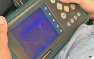
Readiness codes report the availability and status of the monitors through the Select Monitor. While viewing the OBD II section from the engine main menu, the first eight items will indicate No Support, Complete or Incomplete. No Support indicates that the vehicle is not equipped with that system. Incomplete indicates that the vehicle has this system but has not diagnosed this system, but will once the Enabling Criteria have been met. Complete indicates that the diagnostics have been performed for that system. These values will not default to incomplete once they are complete, unless the memory has been cleared or battery power has been removed for more than 10 minutes. (1996 vehicles default to incomplete when the ignition is turned off.) See State I/M Program Advisory Bulletin 11-49-97R. (Located in back of booklet.)
During the actual testing or diagnostics performed by the ECM, vehicle sensors send information to a testing area of the ECM. The information is evaluated to determine if the vehicle has met the enabling criteria and the results of the forced testing of systems are diagnosed.
Each system is assigned to trigger the illumination of the Check Engine Light in either a single fault or double fault occurrence (trip). The single fault trip DTCs will store a memorized DTC and record the vehicle operating conditions (Freeze Frame Data) when the ECM determines a fault exists. The Check Engine Light is also illuminating. Double fault trip DTCs will not illuminate the Check Engine Light when the first fault is detected. It will register the DTC as a temporary code and wait for the second consecutive failed trip to occur before illuminating the Check Engine Light.
The exception to the second fault rule is any DTC that is related to Fuel Trim or Misfire. The second fault trip for these items must occur within 375 rpm and 20 percent of the engine load of the first fault. At that point the Check Engine Light will illuminate, and the DTC and Freeze Frame data will be memorized.
OBD II requirements state that all manufacturers standardize code assignments. Each code consists of five characters.
Malfunction Indicator Lamp Operation
The Check Engine Light, now called the Malfunction Indicator Lamp (MIL), provides communication to the driver and the technician. The steady illumination of the MIL with the engine running indicates an existing problem to the driver. A MIL that is flashing at 1 Hz indicates that a misfire which may cause catalyst damage presently exists (immediate service attention is recommended).
Technician communications via the MIL include three messages. The first is a 3 Hz flash which indicates the inspection mode connectors are connected. The second is a 1 Hz flash which indicates a misfire that will cause catalyst damage exits. The third MIL signal, steady illumination, indicates a problem exists or has recently occurred and a DTC has been set.
DTC Memory
Memory of a DTC (as it relates to illuminating the MIL) is maintained until three consecutive passing trips have been made (the enabling criteria were reached three times in a row and the tests were performed with good results). The MIL will turn off at this point.
The DTC will remain available for viewing with the Select Monitor and the freeze frame data associated with it will remain in memory for 40 warm up cycles.
The exception to this rule is if the DTC is associated to misfire or fuel trim. In this case 80 warm up cycles must be completed before full erasure will occur.
Warm Up Cycle
A warm up cycle occurs when the engine coolant temperature rises to at least 40˚F (22.2˚C) above the temperature at start up, and reaches a minimum of 160˚F (71.1°C).
Freeze Frame
Freeze Frame is a record of the vehicle operating conditions at the moment a DTC is set. These include:
- Engine RPM,
- Engine Load,
- Fuel Pressure,
- Fuel Trim Values,
- Coolant Temperature,
- Intake Manifold Pressure,
- Loop Status,
- DTC causing the MIL to illuminate.
A DTC associated with misfire of fuel trim is considered a high priority. Therefore, the freeze frame data associated with a misfire or fuel trim DTC will overwrite the freeze frame data from all other DTCs.
Fuel Trim
Short-term and long-term fuel trim are visual interpretations on the current (short term) and historical (long term) corrections to the air fuel mixture required to give the vehicle the best driveability and lowest emission output.
The ECM continuously monitors the amount of fuel injected and places the information recorded into memory. The ECM places the memorized information into a position that is referenced by engine load and engine rpm. The next time the vehicle is in those same conditions, the memorized information is compared to the amount currently being injected. A DTC will be registered if the difference between the two is too great.
Download PDF


0 Comments