
BMWs are performance vehicles driven by performance-oriented owners. The way the vehicle accelerates and handles are two of the main reasons they purchased a BMW. So, they’re more inclined to notice peculiar handling characteristics, as well as shifting concerns.
BMW has two automatic transmission suppliers, and knowing what goes wrong, how to handle diagnosis, and how to perform service will give you the ability to keep your customers’ BMW vehicles performing as BMWs are engineered
to perform.
First, what are we working on?
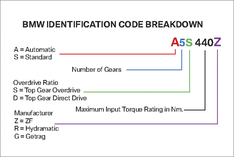
Because BMW has two transmission suppliers, it produced its own alpha/numeric identification system for the different units.
As already mentioned, BMW uses automatic transmissions from two manufacturers. One is ZF (Zahnradfabrik Friedrichshafen), which also produces manual transmissions for BMW, and the other is GM (GM Powertrain). So, there are two possible identification numbers on each transmission. One number is provided by the original equipment manufacturer and the other is supplied by BMW. Obviously, this is important for ordering parts, but most dealer parts personnel will ask for the last seven digits of the VIN to identify the vehicle and its transmission application. When searching for service information, it’s important to know both the BMW designation and the control unit version and/or production date. This is critical when evaluating a wiring diagram or diagnostic service information. Without the proper identification, the system layout, pin location and wire colors may be incorrect. This could lead either to an incorrect diagnosis, or wasted time, or both.
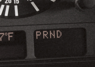
Notice how none of the gear position indicators are highlighted with the key on and the engine running. This is an indication that the gear selector switch is not functioning and the EGS does not know what gear the transmission is in
Because of the two different manufacturers, BMW had to provide its own identification method. This alpha/numeric system gives pertinent information about the transmission. Look at the illustration and you’ll see how BMW identifies the type of transmission, number of forward gears, overdrive or direct drive, torque capacity and, finally, the manufacturer. If you use the identification tag mounted on the transmission, you’ll have to match the manufacturer tag with the service information. Software versions also have an effect on information. Much like on your home computer, a higher number software version means there has been an update engineered into the system. For instance, the EGS 8.34 system uses only one output speed sensor to the transmission control unit. The later system EGS 8.60 uses two speed sensors, one each for the input and output shafts. You can find the version number on the ECM identification screen of your GT1 (or other compatible scan tool).
What are you looking for?
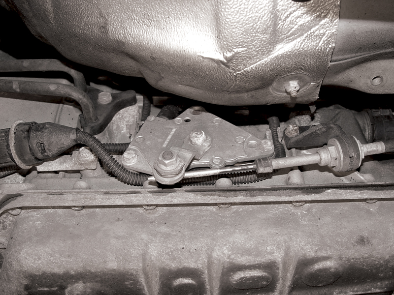
The gear selector switch is mounted on the side of the transmission on this ZF unit. There are a few technical service bulletins to look out for on this switch, so don’t forget to check this first.
When dealing with any customer complaint, it is always a good idea to road test the vehicle, preferably with the customer at the wheel. Watching the way he or she drives may give some indication as to what is causing the problem. If the issue is as simple as a “Service Engine Soon†light (Malfunction Indicator Lamp — BMW doesn’t use a separate “Check Transmission†lamp), then a quick scan for codes and data may give you a diagnostic path to follow. In the case of multiple codes in the transmission and/or engine systems, record the codes and clear them first. After clearing, check for codes with the ignition turned on. This will let you know if there are any “hard†failures happening right now. Also check for codes after starting the engine and after putting the transmission in gear. If you find a code at this stage, either by starting the engine or shifting into gear, it reduces the number of possibilities. Finally, test drive the vehicle yourself and see if any code(s) return.
One quick item to point out is that you should watch the gear position display in the instrument cluster. As you move the shift handle you should see the indicator on the display change from P to R, then to N and finally to D. If you see the indicator disappear, it’s a good indication that the instrument cluster computer is not receiving the signal on the CAN line from the transmission control unit.
The control unit receives the signal from the gear selector switch, which, in the case of a ZF, is mounted on the driver’s side of the transmission. A bad switch contact will send an implausible signal, and the EGS unit will not be able to pass it on to the instrument cluster. Scan the gear selector switch in the transmission control unit and you will see the switch input as you shift through each gear. If you do not see the gear indicated in the data, this indicates that you should test the switch contacts with a voltmeter at the sensor. Keep in mind that these switch contacts should include the “Steptronic†switch, which indicates to the transmission control unit that the shifts will be controlled manually by the driver.
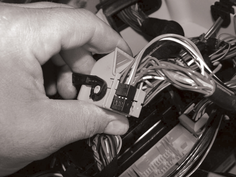
Here is the EGS control unit connector cover. Look for the locking tab. By pushing this tab out you can slide out the wiring connector, plug it back into the EGS and start testing.
The EGS 8.60 system uses speed sensors to determine if there is any slippage between the input and output shafts. This could indicate worn or sticking clutch plates. It could also indicate sticking pistons or solenoids in the valve body. If the problem is worn clutch plates, the transmission is going to need to be overhauled or replaced. However, it would be a very embarrassing mistake to do that job only to find out that shift quality problems were caused by sticking shift solenoids. Using a scope you can monitor solenoid control while driving, or you can activate the solenoids through your scan tool and monitor the voltage/current draw of each solenoid. You can perform these voltage drop and current draw tests at either the EGS control unit, or the connector at the transmission. Either way will allow you access to the wiring you are concerned with. By accessing the wiring at the control unit, you will also test the entire wiring harness. If you chose to perform your testing at the transmission connector, you may be able to isolate the cause more quickly.
Six of one, half a dozen of the other
If you remove the cover to the E-Box you will see the powertrain system computers. Removing the transmission control unit’s connector covers (blue) will give you access to the pins on the control unit for voltage and current testing. To remove the connector covers, simply unplug all the connectors involved to get at the one you need. On one side of the connector cover you’ll see the tabs that lock the wiring connector into the cover. After you slide off the covers, you can carefully plug the wiring connectors into the EGS control unit and begin testing.
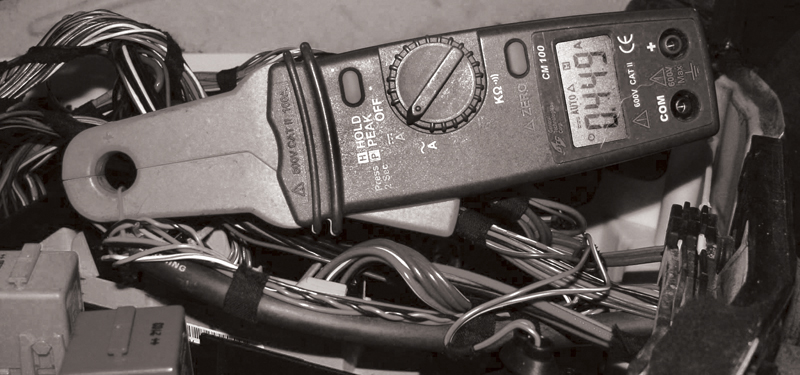
You can check the current draw with an inductive amp probe. In this case, one of the pressure regulator solenoids is being checked while it is activated.
Using your scan tool, you can activate each of the shift and pressure solenoids and monitor their voltage/current. An inductive current probe will give you an overall view of the amperage drawn by each solenoid. Each pressure regulator solenoid draws about half an amp, whereas ach shift solenoid draws just under half an amp. If you need to take solenoid operation a little further, you can scope the solenoids and monitor the waveform patterns.
While monitoring the pressure regulator solenoid, you’ll see that the EGS intermittently grounds the solenoid very quickly and it’s not even activating the solenoid (why it does this is not important for this discussion). The solenoid is not grounded for very long and therefore not enough electro-motive force is generated for activation. When you activate the solenoid through the scan tool, you’ll see that the voltage signal is pulled to ground much longer. The solenoid is activated and as a result you can now measure the amperage draw.
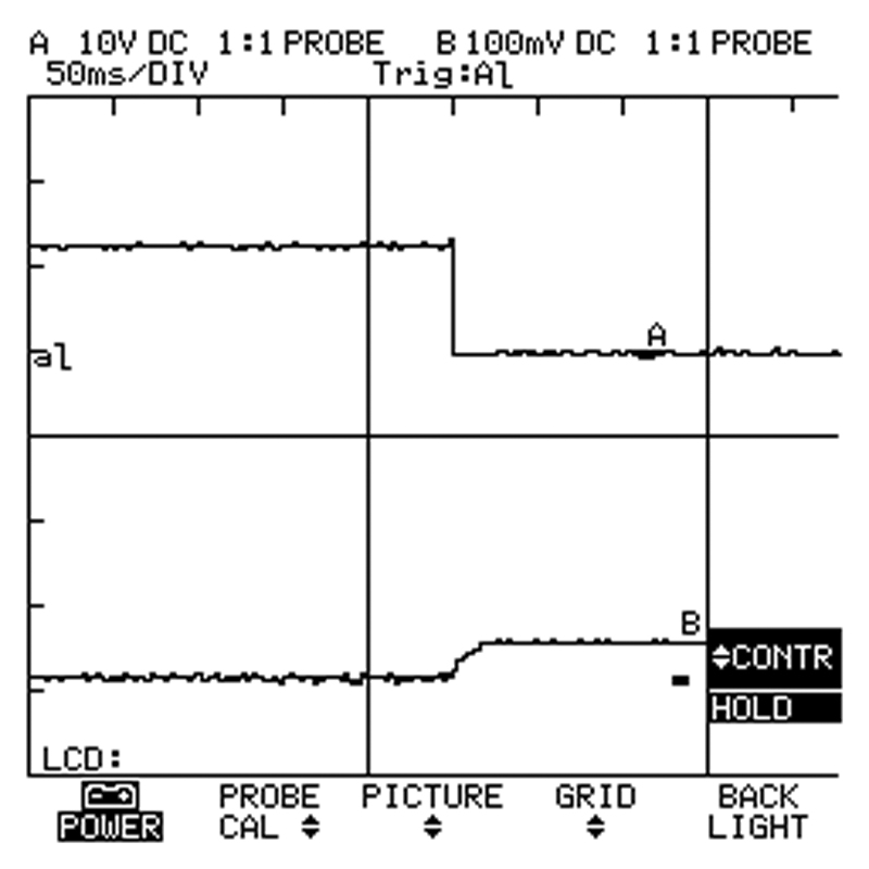
Here, the voltage control (upper trace) and amperage draw (lower trace) of a shift solenoid are being monitored. The resistance of these solenoids is about 30 ohms. In this case, the low current probe was set to put out 100mA per amp, so with the scope set to 100mA divisions we see just below .5 amp.
If you would rather perform your electrical tests at the connector on the transmission, this is possible also. This is a good idea if you suspect a problem with the harness in the transmission. To unlock the connector at the transmission case, you have to pull on the cam lock of the connector and then pull the connector backwards. Now would be a good time to check for corrosion in the connector.
Once again, it’s important to know the production date of the vehicle you are working on. On this E39 chassis, you will find that the wires that provide voltage to the solenoid are different from one year to the next. For instance, from 9/1998 to 9/1999 pin #12 provided power to the four pressure regulator solenoids, and pin #16 provided power to the three shift solenoids. After 9/1999, pin #12 provides voltage to pressure regulator solenoids 2 and 3 only. Pin #16 provides voltage to the rest of the solenoids.
It is not difficult to drop the transmission pan and expose the solenoids. You can also remove the securing clip of the connector and remove it from the housing of the transmission to check the wiring harness more easily. When checking the resistance of the solenoids you will see just under 30 ohms for the shift solenoids and just over six ohms for the pressure regulator solenoids. According to Ohm’s Law, the shift solenoids reading makes sense, but the pressure regulator solenoids should draw about two amps. The answer is that the EGS unit controls the current flow, so that’s why when you activate the solenoid you only monitor about .5 amp.
The right ATF is crucial
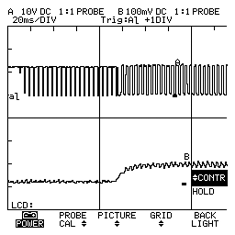
The voltage control (upper trace) and amperage draw (lower trace) of a pressure regulator solenoid are shown here. This solenoid is current-limited by the EGS unit. The solenoid is pulsed to ground, but there’s no current draw. When the EGS activates the solenoid, it increases the duty cycle to ground, which in turn operates the solenoid.
On the GM four-speed units such as the A4S 270/310R previous to ’98, you can use Dexron III. After ’98, BMW introduced five-speed transmissions manufactured by GM. On these, check the sticker affixed to the transmission pan, which indicates the type of automaticv transmission fluid that was used at the factory. The GM units use Texaco ETL-7045E, or ETL-8072B, which are available at your BMW dealer’s parts department in 25 liter containers.
In ’92, BMW started to phase in the five-speed ZF transmission. These use Esso LT 71141, or Shell LA 2634. Only the E34 530i/iT had the A5S 310Z that uses Dexron III fluid. The Esso ATF is available in a 20-liter container and the Shell comes in a five-liter bottle. BMW has saved you the trouble of looking it up by printing the part number for the oil right on the sticker.
A proper finish
As with any automatic transmission, fluid level can have an effect on shift performance, so it must be correct. One of the conditions for accurately checking the level is making sure the fluid temperature is between 30 and 50 deg. C, which you can read on your scan tool. Have the engine running, turn on the A/C and set the blower motor to maximum speed. It’s not that BMW wants you to be comfortably cool while checking the fluid level, but that the resulting increase in idle speed will help the transmission pump produce more pressure and volume. This will be needed because the next step is to move the shifter into each gear. This ensures all the valve body channels are filled with transmission fluid. At this point, you can check the level. If you have a dipstick, use it. On vehicles without a dipstick, remove the fill plug on the pan of the transmission and watch. You should see a stream of transmission fluid run out of this hole. If not, add fluid at the fill plug until it starts to run out and install the plug
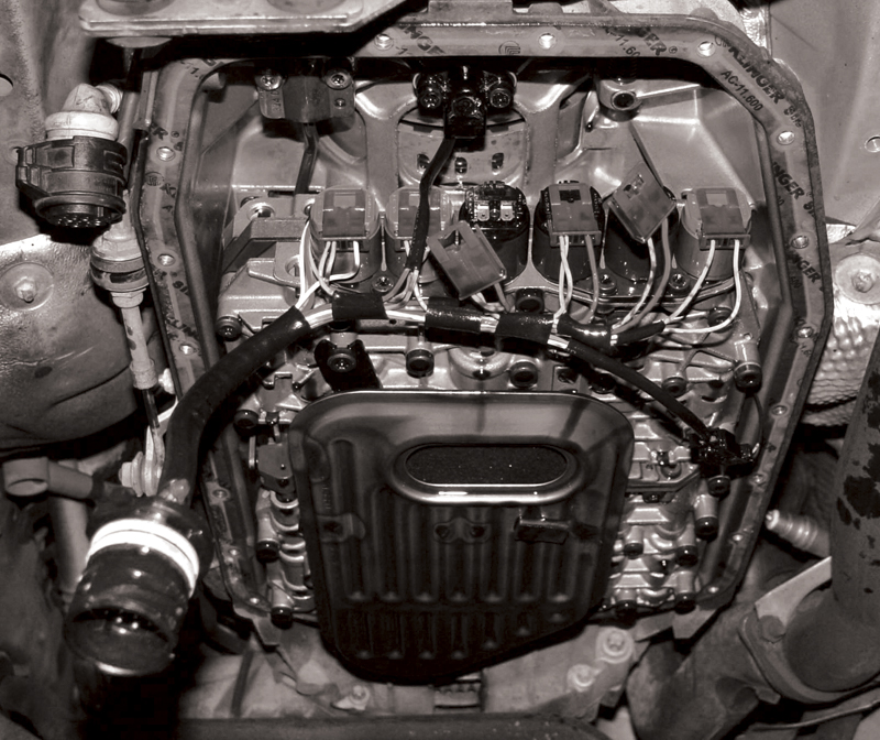
With the pan dropped and the connector removed, you can easily check the wiring harness inside the transmission. You can also check the solenoid resistance directly. The green solenoids are the shift solenoids and the black solenoids are the pressure regulator solenoids.


0 Comments