
One of the first major advancements that used a computer to assist with vehicle safety is the anti-lock braking system. The premise is simple: To slow down the vehicle as fast as possible by maintaining traction between the tires and the road. If the braking force overcomes traction and the wheels lock up, it reduces hydraulic pressure to the brakes. Once the wheels regain grip, it quickly reapplies the pressure. Obviously, it’s important to keep this system functioning properly for the safety of your customer. Depending on what is wrong, a repair may be expensive, but the cost of an accident will far outweigh the money saved in not repairing the system. Let’s see how we can keep the diagnosis and repair profitable, and at a cost your customer sees as a wise investment.
Who Is Involved
Knowing how the components function will help you diagnose any problem. As with any computer-controlled system, by definition a computer processor must be present. This is the main brain of the ABS. It receives inputs from sensors, processes the information, and, depending on programming, manipulates outputs. These output controls actively change the way the vehicle behaves. In the case of the ABS, it controls the hydraulic pressure applied to the calipers. It applies fluid pressure when the wheels have traction with the road. When lockup occurs, output controls will reduce brake pressure and allow the wheel to regain grip.
For decades, BMW has incorporated self-diagnostic features into the control unit for the ABS. When the ignition key is cycled on, the ABS control unit goes through a “dynamic circuit check.†That is, it monitors input circuits for incorrect voltage readings, such as electrical shorts to power or ground. It does the same for output controls. It monitors the voltage on the wires going into and out of the control unit. If there is a problem, the computer activates a warning light indicating to the driver that the ABS will not function as designed. The ABS light will come on for a bulb check with the ignition key turned on, and it will remain on until all circuit tests are complete. At this point, if all the tests are passed the light will go out. If a test fails the light will remain on.
Inputs
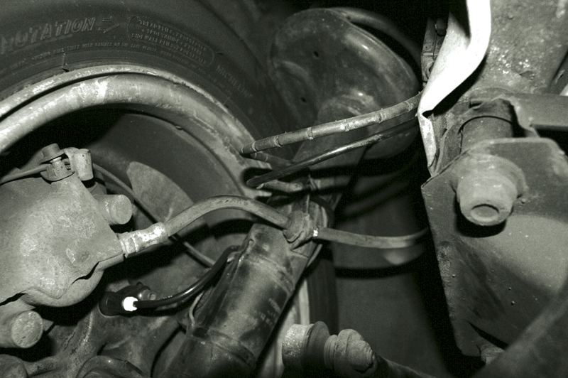
Pictured here is a new left front wheel speed sensor. Notice how the wiring is positioned around the strut assembly. This way, as the wheel is steered the wiring is not stressed. Make sure the wiring is not damaged when replacing the sensor. Damaged wiring may have been the real cause of the problem.
Input sensors are critical to ABS operation. The main sensors that allow the ABS to function are the wheel speed sensors. These are generally mounted on the spindle of each wheel, and they read the movement of a toothed ring gear mounted on the rotating hub assembly or axle. One type is the AC pulse generator, or inductive speed sensor. These have a winding or coil wrapped around an iron core. As the teeth of the ring gear or tone wheel pass by the sensor, a voltage increase is induced in the winding. This induction produces a spike in the AC voltage traveling on the wire from the sensor to the ABS control unit. As the tooth passes by the low point of the ring gear, the AC voltage changes direction and the voltage drops low. The frequency of the high/low voltage swings is directly proportional to the speed of the hub. The higher the frequency, the faster the wheel is spinning.
On some models another type of wheel speed sensor is used. This is known as a Hall-Effect or “Active†sensor. This still reads wheel speed off a tone wheel, but it receives a reference voltage from the ABS control unit. As the ring gear passes by the sensor a magnetic field toggles this reference voltage to ground. This generates an on/off square wave instead of an AC voltage sine wave.
If one wheel signal were to drop faster than the other wheel speed signals, then you could conclude that this one wheel is slowing down faster than the others, or “impending lockup.†This is how the control unit determines which wheels have lost traction and which have not. These are obviously important inputs and must be tested with the same scrutiny as any sensor in a safety-related system. The ABS control unit also passes on the speed sensor inputs to other control units such as the DME, EGS and Kombi-meter (Instrument Cluster).
Other important inputs are obvious. One is the brake switch. This tells the ABS computer that the driver has applied the brakes. Another sensor found in later ’90s vehicles where ASR and DSC are added is a brake fluid pressure sensor. This monitors the pressure in the braking system at all times, even when the brakes are not applied. If the brakes are not applied (brake switch input) and a wheel is losing traction (wheel speed signals not matching), it can be assumed the tire has lost traction under acceleration, and the brakes are applied to the slipping wheel until the wheel speeds match.
Outputs
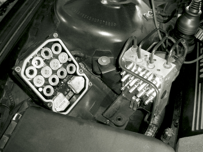
The hydraulic pump contacts are hidden between the ABS control unit and the hydraulic assembly. It would be difficult to test the pump without a GT1 scan tool. When servicing the control unit make sure these contacts are clean. Carbon indicates arcing, which could mean excessive current draw.
We know in order to control traction we need to control brake fluid pressure to the calipers. By applying and releasing brake fluid pressure, we can gradually slow down the wheel without losing traction, allowing the driver to focus on steering. Brake pressure at each wheel is controlled by two solenoids. One is an inlet solenoid and the other is an outlet solenoid. The inlet solenoid is normally open allowing fluid pressure to reach the calipers. The outlet solenoid is closed. Under an ABS brake stop, if the wheel is locking up the inlet solenoid is closed and the outlet solenoid is open, therefore reducing brake fluid pressure. As the wheel starts to regain grip, the solenoids reverse, opening the inlet solenoid and closing the outlet solenoid and the vehicle continues the braking process. This system alternates these solenoid activations until the vehicle is brought to a controlled stop. The brake pedal generates the initial brake fluid pressure to stop the vehicle, but during an ABS stop this is not enough.
Another critical component in the system is the ABS Brake Hydraulic pump. This pump is usually activated with every key cycle to test its operation and make sure there is necessary brake pressure in the system. It is more than likely built into the hydraulic assembly, which is the solenoid pack, ABS pump, and, in most cases, the ABS control unit.
Testing, Testing, Testing,…
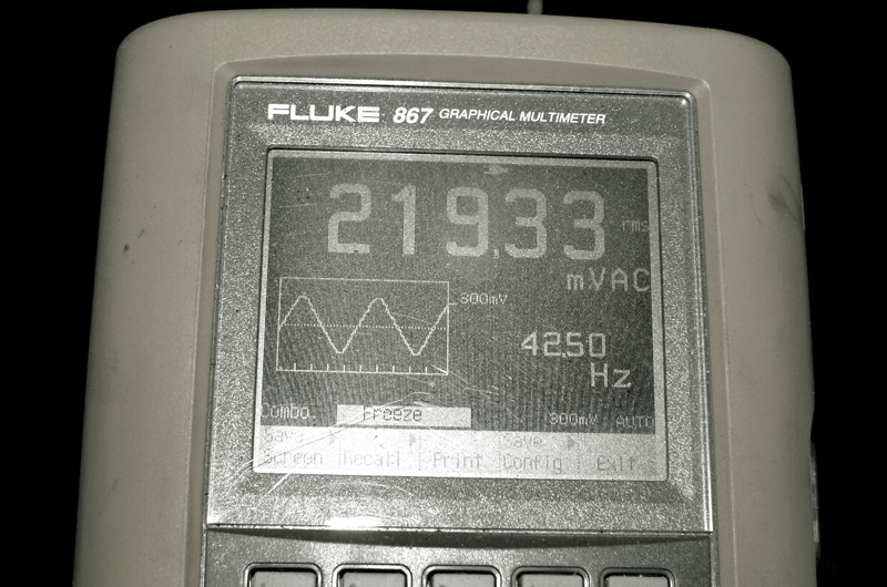
Here we have a wheel speed sensor signal captured by a graphing multimeter. Notice the 219mv sine waveform. This voltage will go up slightly with wheel speed, but notice in the lower right hand part of the screen the Hz reading of about 42. This will increase proportionally with wheel speed.
When the ABS light is on, we know the system has either lost power, or has detected a problem. Check all constant and ignition-on power supplies to the ABS control unit, as well as ground wiring. If there is a problem, fix that first. A bad ground is as bad as a blown fuse. If powers and grounds are all there, we can now move on to self-diagnostics. With your GT1, or equivalent, you can access diagnostic trouble codes and see what self diagnostics have found wrong with the system. Fault tracing the trouble code with the appropriate BMW flowchart should bring you to a conclusive diagnosis, but many problems can occur that fall outside the box.
Testing wheel speed sensors is probably the most common test for an ABS fault. A preliminary test of the sensors would be to monitor data on the scan tool while driving the vehicle to see if all the sensors indicate the same wheel speed. Keep in mind as you go through turns the front and rear wheels will travel at different speeds, and this is to be expected on a road test. Driving straight, all the wheels should indicate the same wheel speed. If you have the ability to graph the data, you may want to see if any of the signals “drop out†while driving. Of course, in the interests of safety, have someone drive the vehicle while you are observing data, or recording a movie of the data, and review it after the road test. Almost all of the data we are concerned with can be observed through the scan tool. Support the data with direct electrical testing to verify wiring as well as component function. This applies to outputs as well as input sensors.
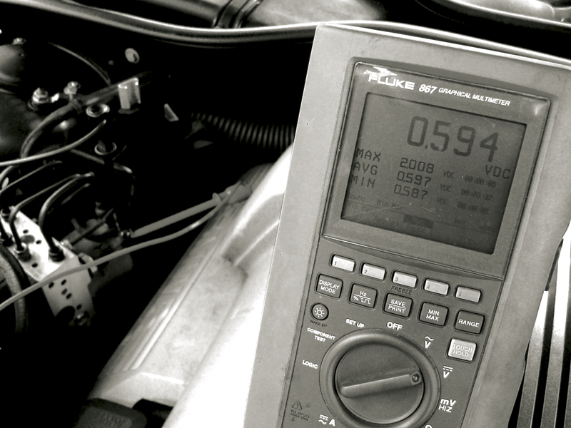
Checking the voltage at the pressure sensor (if equipped) can allow you to easily check the brake fluid pressure under different conditions. Notice how we have .6 volts KOEO, and after pumping the brake pedal this increases to a MAX of 2.0 volts. It is important that you verify that the three-wire sensor has a good five-volt reference and ground before we can trust the readings.
In the case of the pulse-generators, we know that they are two-wire sensors. These sensors have a winding within them so we can measure resistance and see if the winding is intact. If the resistance is acceptable, that is only half of the equation. The next step is to monitor the AC voltage coming out of the sensor. Since the sensor generates its own voltage from the movement of the ring gear, spin the wheel to measure its output. The amount of voltage is important, but more important is the voltage signal in comparison to the opposing wheel’s voltage signal.
If the problem is still not evident, you may need to scope the two signals in real time and see if the patterns’ amplitude and magnitude equal one another. In the case of the Hall-effect sensor, the amplitude and magnitude of the signal will not change. Only the frequency will change. If the amplitude and magnitude of the signal did change, we would have to test the reference voltage from the control unit to see if it is stable — usually about 8.0 volts, depending on the system you are working on. You may still need to lab-scope the signals to see if there are any glitches. This can also indicate a cracked ring gear that the ABS control unit may interpret as a bad sensor.
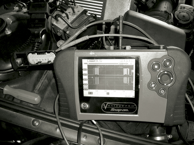
If codes tell you several control units cannot communicate with the ABS unit, you need to check the unit. After verifying powers and grounds, scope the CAN lines and see if you see a CAN waveform. You may want to compare the waveform with that at another control unit. This verifies CAN wiring is okay.
While the brake switch input is as simple as an on/off voltage switch, some of the other outputs, such as the inlet and outlet solenoids, are not simple to test. With the key on, all of the solenoids are powered up through a relay (either separate or built into the ABS module), and the ABS control unit monitors the voltage drop on the ground control side of the solenoid. If we have 12 volts going into the solenoids, we should have close to 12 volts on the ground control side of the solenoids. Then the ABS control units cycles the solenoids and monitors the voltage drop and amp draw on each one. In some cases we can perform the same testing; in others we cannot. If the solenoid pack is a separate serviceable item, we can power up the solenoids and watch ground control voltage and monitor the amperage draw. These days, the solenoids are incorporated into the ABS control unit and we can only monitor solenoid amp draw by testing it at one of the power supply wires while using our scan tool to activate the solenoid. This type of in-depth testing is often not required since the ABS solenoids are serviced as a unit.
If you have a diagnostic code for the ABS pump, how are you going to test that? These pumps generate quite a bit of pressure and do it quickly. The amp draw is monitored by the self-diagnostic portion of the ABS control unit to determine if it is functioning properly. On later systems, the brake fluid pressure sensor helps determine if the pump is up to snuff. If the amp draw is incorrect, a diagnostic trouble code will be set and the ABS warning light will remain lit. You can test the pump one of two ways. You can monitor the current draw while it is being activated and compare our findings to a current ramp pattern of a good pump. If you have determined that the pressure sensor is functioning properly, you can activate the pump and either watch the pressure reading on your scan tool, or monitor the signal voltage on the pressure sensor. If you see the pressure sensor voltage drop off, make sure the pressure sensor has its proper five-volt reference. If the five-volt reference is also dropping with the signal voltage, then you may need to look deeper into the ABS control unit function.
Other Faults
If your scan tool cannot communicate with the ABS control unit, you should immediately try to establish communication with other control units on that same CAN. If you cannot communicate with any of them, you need to test the CAN wiring. If you can communicate with other units, see if there are codes in these units. You should see codes for a loss of communication with the ABS control unit. This is a sign that the ABS unit has failed. To verify your findings, you need to scope the CAN data lines into and out of the ABS module to test for bad wiring. If the wiring is good, then you more than likely have a bad unit. You will also need to test the power and ground supplies to the unit to make sure it has everything it needs to function.


0 Comments