Being in the luxury segment means BMW vehicles provide great creature comforts as well as high performance. So, keeping their climate control systems functioning properly should be a high priority for you.
With cold weather closing in upon us, your customer’s attention may turn toward comfortable warmth. The days are getting shorter, children have returned to school, and on cold mornings they’d better have heat in their BMW’s! Inform your customers that even in this hectic life we live they should still take the time to properly warm up their vehicles, which will extend engine life. After a short warm-up they will not want to be feeling cold. BMW has advanced its climate-control systems to address the driver’s concerns, such as quickly defrosting the windshield and sufficient heat provided quickly.
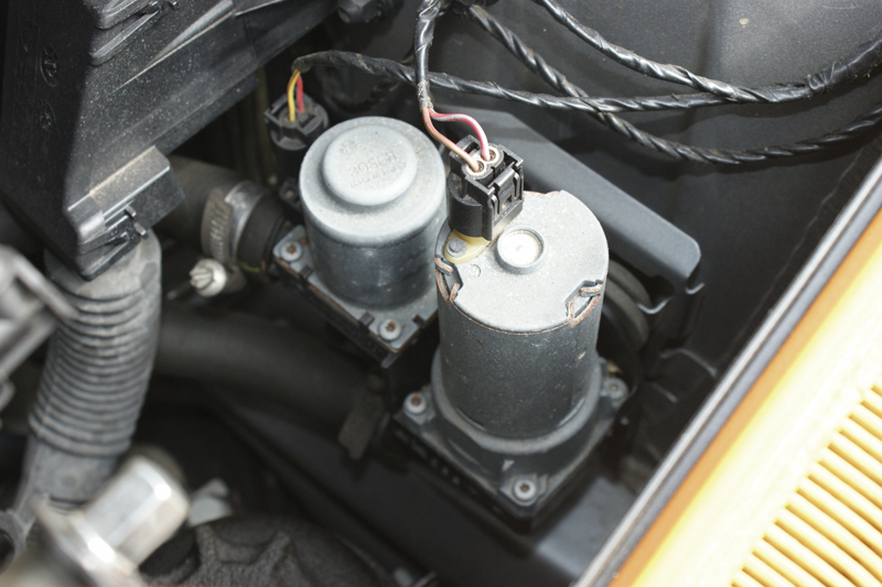
This single heater control valve is mounted behind the auxiliary coolant pump. It determines how much coolant makes it to the heater core, and the auxiliary coolant pump assists flow when heating demand is high.
In previous issues of TechDrive, the air conditioning portion of the overall HVAC system was covered in depth. IHKS, IHKR and IHKA were reviewed, leaning toward A/C compressor operation and engine management system integration. Now, let’s turn our attention toward keeping our customers warm.
Controlling the blower motor speed is obviously important, and has advanced from simple parallel circuits with a matrix of resistors of different values to a more sophisticated solid-state module capable of many more speeds, and which can respond to changes in demand automatically.
It’s Getting Hot In Here
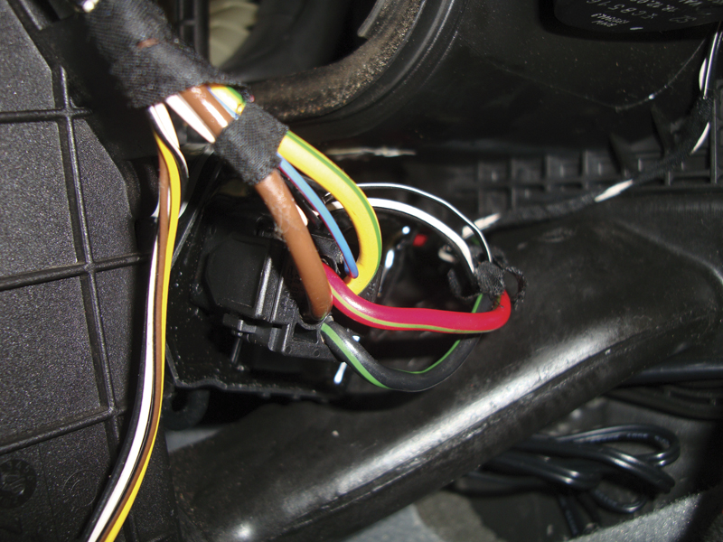
The final stage unit is usually located behind the glove box. The yellow wire with a green tracer is the power supply from the heater relay, the brown wire is ground, and the red wire with a green tracer is the power supply. The black wire with a green tracer is the ground supply to the blower motor, and, finally, the blue wire with a red tracer is the control wire from the IHKR or IHKA control units.
While the conventional thermostat and heater core have been supplying heat for passengers for decades, over the past 20 years BMW has improved its systems with the addition of an auxiliary water pump. With added heater cores for dual- and multiple-zone systems, coolant plumbing has become more complex. With this additional piping and sharper angles, coolant flow is often compromised.
To help maintain flow, the auxiliary coolant pump is used to maintain flow through the additional hoses whether the thermostat is open or closed. Also, it allows the coolant that is heated by the engine after start-up to quickly get circulated through the vehicle’s heater core(s). The auxiliary coolant pump is only activated when heating demand is high. The IHKS, IHKR, and IHKA control unit manages the operation of the pump when the interior temperature is approximately five deg. F. colder than the selected temperature. The pump is typically mounted on the coolant return side of the heater core(s), sending coolant back to the water pump. This allows even coolant flow through each heater core even on multiple-zone temperature-controlled systems. The pump works in conjunction with a heater control valve.
The heater control valve has been used by BMW for approximately three decades. It manages the flow of heated fluid into the vehicle’s cabin. Instead of using a cable or vacuum control to open and close the valve, BMW opted for electronics. The IHKS (R, A) control unit uses a pulse with modulated signal to open and close the valve depending on the selected temperature. This valve controls the heated coolant flow even if the auxiliary coolant pump is not operating. The heater control valve is often mounted near or with the auxiliary coolant pump on the return side of flow. Single temperature controlled systems only use one heater control valve, whereas on dual-zone systems a “duo†valve is used. It’s simply two separate heater control valves sharing the same housing and return line. Each valve controls coolant flow to its respective heater core. Now that we have heat inside the vehicle, how do we circulate it throughout the cabin.
The job of the blower motor is to move air around the cabin. It takes the temperature-controlled air from the HVAC housing and distributes it. To accommodate passenger comfort, the rate of air flow can be changed with fan speed. The task of controlling fan speed is now handled by a solid state device known as the blower motor control unit. Yes, it has achieved “control unit†status.
In most applications, the blower motor control unit, (aka “final stage unit, or “transistor output stage”) is fed power through a relay. The relay supplies power providing the ignition switch activates the relay. Once activated, the final stage controls both the power supply and ground to the blower motor. It can vary the ground potential of the blower motor to increase or decrease fan speed. The command to increase and decrease blower speed is also supplied by the IHKR (A) control unit to the
final stage unit.
Who Pulls Whose Chain?
By now, you should have determined that the central control of the heating system is the IHKS, IHKR, or IHKA unit. IHKS is a manual system that still uses electronic controls to set temperature and blower speed, but does not provide feedback as temperature conditions change. Mode door control is manual. IHKS can be identified by three round dials for temperature, mode door, and blower speed, but it only has a switch panel with a remote-mounted control unit. It also uses a resistor pack to vary blower motor speed, not a final stage unit. The IHKR system does provide feedback for changes in temperature and blower speed, but mode door control is still manually controlled. It also has three dials, but the control unit is incorporated into the switch assembly. Finally, IHKA systems are electronically controlled, and in “Auto†mode can automatically change mode doors, temperature compensation and blower speed. Once again, the switch unit is also the control unit.
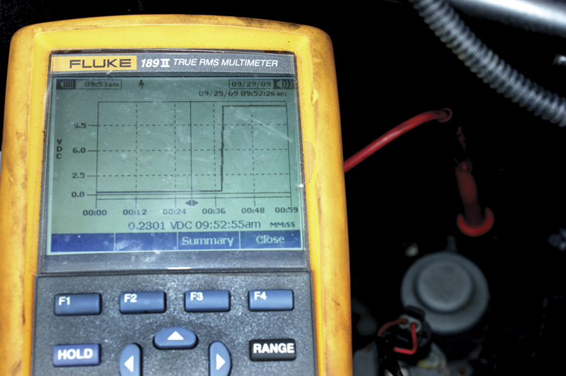
Look at the voltage command of the heater control valve and you see that at the beginning of the graph the voltage is low. This is the valve commanded closed for A/C operation. As you increase the temperature in the cabin, you eventually see the valve being “ungrounded†toward the end of the trace and therefore opening for maximum heat.
Testing One, Two, Three
Whether the complaint is insufficient heat, or no blower operation, you now have won half the battle by knowing what the various components are and what is involved in supplying heat. If you are going to diagnose this problem, you’re going to need some testing procedures. Some of the symptoms you have to contend with are inadequate heat, lack of heater control, the inability to control each dual/multiple temperature zone, no blower motor control, or the blower is stuck at one speed.
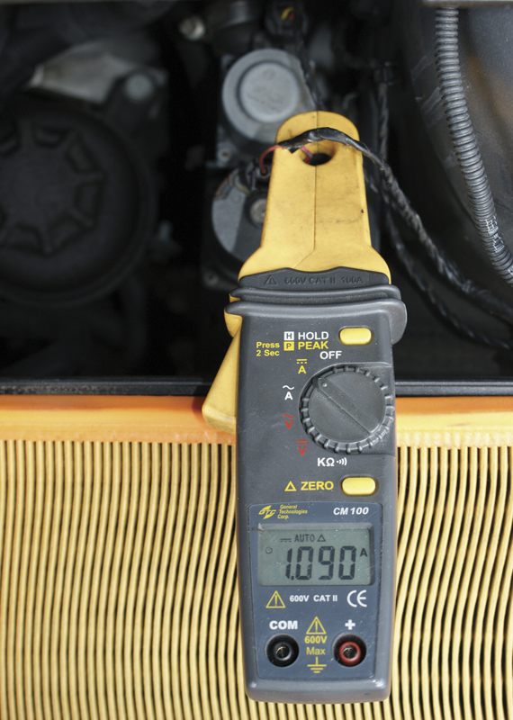
With the temperature set above 80 deg. F., you should see the auxiliary coolant pump activated. It should draw about one amp at full speed, but it’s normal for a cold engine to increase that drawto about 1.3 amps.
How are we going to approach these various problems? Let’s start by looking at the heat situation. The electronically controlled heater valve, or duo valve, depending on the application, is normally open. That is, it passes coolant when not energized. This gives maximum flow and therefore maximum heat when there is no power to the system. When there is a failure in the system, at least the vehicle still has heat for defrosting purposes, etc. You can use this operational strategy to your advantage by simply unplugging the valve and seeing if the input and output hoses read the same temperature with a non-contact infrared thermometer. If yes, then the valve is open. If not, the valve may be stuck closed. The same operational characteristics apply to the duo-valve. When you have a vehicle without independent control of temperature settings you may have one of the channels of the duo-valve stuck closed.
With the valve(s) wide open, you should get maximum heat. In order to reduce heat and increase cooling during the summer months, the circuit(s) of the water valve are energized or grounded. This closes the valve and reduces the heat inside the HVAC control assembly under the dashboard. With the heat reduced, the A/C system can work more efficiently. If you notice the A/C system is a little warmer than normal, but the refrigerant high- and low-side pressures read normal for your ambient temperature, the water valve(s) may be stuck open. The water valve(s) is controlled by the IHKS (R, A) control unit. You can monitor the voltage sent to the water valve to close the valve as well as checking resistance between the solenoid(s) of the system you are working on. In some cases, the water valve solenoids are grounded and the control unit supplies power to close them. In other cases, the valve is supplied with a fused power supply and the control unit grounds the solenoid to move it to the closed position. Obviously, check the wiring diagram of the variant you are working on so you know what signals you should be testing for. The voltage control does pulse on and off, but very slowly. You will see a square wave if the time frame on your scope or graphing multi-meter is very slow. These signals can easily be monitored by a conventional DMM. You can supply your own power and ground to manipulate the heater valve, but do not test for too long as current is no longer controlled and excessive current can damage the valve. It takes under a minute to open and close the heater control valve(s).
Auxiliary coolant pumps typically draw about one amp, but can go up to 1.3 amps on a cold motor. If the draw is too low, you probably have a weak pump that’s not sending sufficient coolant to the heater cores. If the amp draw is high, you may have a blockage in the system. This could be from corrosion, as well as a from a stuck-closed heater valve.
Solid State For Solid Performance
With blower motor controls, you should do some digging before you condemn a component, and after you have checked the basics, such as a blown fuse. The blower motor fuse is typically located in the main fuse panel either under the hood in the E box, or behind the glove box. In most cases, to gain access to the blower motor final stage you need to remove the glove box from the vehicle anyway. Now, you can access the final stage connector to perform testing. Being a solid state device, you will see an ignition-on power supply from the heater relay, a direct ground wire, the two power and ground supplies directly to the blower motor itself, and, finally, the control wire from the IHKR (A) control unit. With no blower or fixed speed operation, you should check the voltages at the final stage unit. Since the heater relay supplies battery voltage to the final stage unit, there is the possibility of voltage drop across the contacts of the heater relay. This would supply a low voltage to the final stage for it to operate properly. The final stage also needs a constant ground supply. This ground it typically mounted underneath the driver’s side or passenger’s side seats on a bus bar ground. You can unplug the final stage connector and jump the power supply and ground wires directly to the blower motor wiring to verify that the blower motor is operational. Check the blower motor amp draw to make sure it is not going to damage another final stage unit if replaced. A typical blower motor will draw about 30 amps at full speed. Anything higher than that may overwork a new final stage unit and cause premature failure.
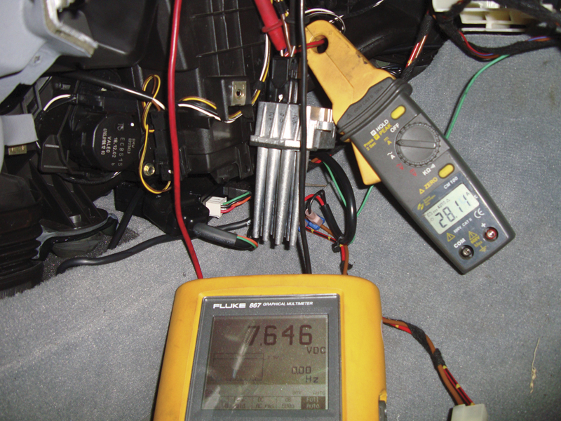
Here we are measuring the amperage draw of the pump with an inductive amp probe while monitoring the command to the power stage with a graphing multi-meter. As you can see, at maximum speed the analog voltage signal is about eight volts, and the blower draw is about 30 amps.
Once the power/ground supply and the blower motor have been checked, you can evaluate the control signal from the IHKR (A) control unit. This can be done with a voltmeter, or scope. The voltage control signal is analog, not digital. Simply monitor the analog voltage signal as you manipulate the blower motor speed control button. With a low-voltage signal, you should have low blower speed. With a higher voltage signal you should notice blower speed increase. In the “Auto†mode, you may notice the signal voltage to the final stage reducing as the interior temperature reaches the selected value. If you use a aftermarket scan tool to monitor this voltage, some of the programming may be incorrect. The voltage signal does not vary between zero and five volts as indicated. The voltage actually increases from just about zero volts with the system off to around eight volts with the control unit commanding maximum blower speed. If the signal is changing between zero and eight volts, you know the control unit is doing its end of the work. If you have a blower speed problem at this point, your problems is with the final stage unit.
In Conclusion
BMW vehicles are technological marvels on multiple levels, but something as simple as insufficient heat or no blower motor can leave your customers out in the cold. By diagnosing and repairing their vehicles with BMW genuine parts you can be sure they’ll ride in the comfort they are entitled to expect. Job well done.


0 Comments