
As every technician knows, one of the most challenging tasks in the automotive field is electrical diagnosis. This is compounded by ever more complex vehicles. Whether it is for efficiency in manufacturing, or for more integrated features, electronic control units are being asked to handle almost every aspect of motorized transportation. While this does lead to a reduction in wiring, it also makes factory self-diagnostic software essential to diagnosing problems in these integrated computer networks.
Regardless of all the new complexity, you still need to come up with a diagnostic plan that will find problems efficiently and effectively, thus allowing your shop to remain profitable. With electrical problems, inadequate supply voltage, component current draw and excessive voltage drop add up to troubleshooting complications. An essential here is understanding how the circuit works, but this is one aspect we are in control of. Knowing how to read and interpret BMW wiring diagrams accurately is half the battle (the other half is actually testing voltages, resistances and amperages). Here, we are going to review navigating the BMW website for the proper wiring diagrams, and some of the benefits of BMW factory wiring.
Beginning
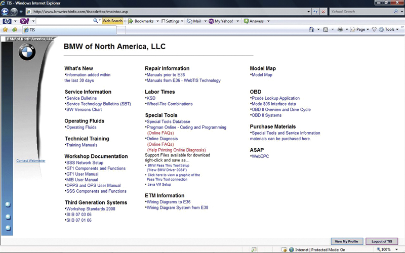
our paid subscription to www.bmwtechinfo.com gets you access to factory service information. Under “Wiring Diagrams,” select “Wiring Diagram Systems from E38†and you will be directed to installing WDS wiring.
At the beginning of any diagnosis, you need a firm grasp of the symptoms and what systems on the vehicle could possibly cause them. Before you start ripping off panels and covers to access wiring, you should pull up the wiring diagrams for the circuits you believe might be at fault. With your paid subscription www.bmwtechinfo.com, you will have access to accurate factory diagrams. This is especially valuable when it comes to the variants of the model — not only the various options, but also any changes that may have occurred from one production run to another. This vehicle-specific information is not always available from the aftermarket information sources you may currently be using.
On the homepage under the heading “Wiring Diagrams,†you will see two options. The first is for selecting the E36 chassis or earlier vehicles. These are PDFs (Portable Document Files), so you will need to have Adobe Acrobat Reader on your computer to view them. They are scanned images of factory paper manuals. You navigate through the various pages by scrolling with the bar on your right and at the bottom just as you do with any file folder in Windows or MAC Explorer. All the information is there, you just have to move the screen around to see it because these pages were not intended to be PC-based. Your other selection is for BMWs built after the E36 chassis, which are probably most of the vehicles you work on. These diagrams were constructed with PC navigation in mind, so all of the variations are laid out like the folders in Windows Explorer, but more on that later.
After selecting post-E38 diagrams, you are directed to the next page where you will select BMW wiring diagrams and the language you would like them displayed in. You are then directed to another page called WDS BMW Wiring Diagram System. If you are using WDS for the first time, you will need to install a plug-in that is available within the WDS website itself. You can do a system test to verify if your PC is capable of running WDS. This test is found on the lower left-hand corner of the installation page. On the right side of the page you’ll see where to download and install the SVG plug-in.
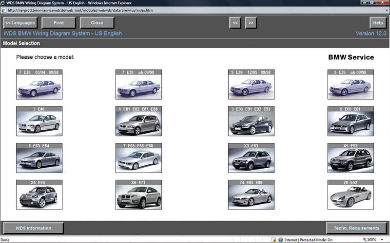
Once WDS is started and the plug-in is installed, you will see the main navigation screen. Select “Complete Vehicle†and pull-down menus will start to appear just as they do in Windows Explorer on your PC.
With all this complete, the WDS home page is displayed with large picture icons of BMW models by chassis number and model series. There are variations in production dates, so be sure to accurately select the vehicle you are working on. Once you have selected a chassis/model, the next page is split in two. The left side of the page is for navigation, and the right side is where the diagram is displayed. If you’re familiar with Windows Explorer navigation you should have no problem here. When you click on the “+†symbol to the left of the heading “Complete Vehicle†once, or double-click on the heading itself, a pull down menu with three more selections is displayed. Your options are “Drive,†“Chassis†and “Bodyâ€. Select the field for which you want to view all the available diagrams.
Here is where you need to pay close attention to your selection. Very often in a single chassis there are variants that are the result of modifications or developments during the vehicle’s lifespan. One chassis can have several variations in any of its systems. For instance, the E46 chassis has seven different variations for the engine management (DME) system and five for the transmission (AGS). One of the easier ways to determine what system is in the vehicle is to plug in your scan tool and actually look at the initial screen once you have communicated with the control unit. If the system ID is not displayed here then select “Control Unit ID†and your next page will illustrate what type of system is used, and hardware, software, index and coding ID numbers. Back in WDS, select the system that matches. Also, watch for production date cut-offs, country produced for, options (ASC or DSC, for example). etc.
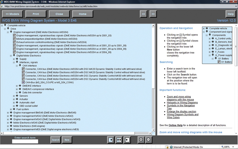
The first critical step is selecting the correct wiring diagram. You will need to choose among all the different variants of the vehicle. This can include production dates, options (ASC or DSC, for example), body style, left/right hand drive, version level, etc.
This is where technicians might get into trouble. By not selecting the correct diagram, you may end up finding wiring that does not match the vehicle, or looking for wiring that is not there. For example, if you need to know if the vehicle has ASC or DSC, with the ignition key on look for either a DSC on/off switch mounted near the center console, or use your factory software to scan for all modules. On factory software, this is referred to as a “Short Test,†or on later releases a “Quick Brief Testâ€. Here the ZCS coding is read off the vehicle and all possible modules for that model are displayed. Unless there is a communication problem with one of the various bus systems, this is the best way to identify the variants.
The Easy Part
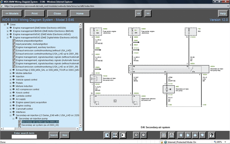
Now that you have a diagram up, you can follow the wiring. You should be able to determine which wires supply power, what the component does this power, and how the components are grounded. Your testing of these factors is next.
Once you have selected vehicle options, another pull-down menu will be displayed. You will see a combination of diagrams listed at the top, and just below these are more sub-folders to choose from. The diagrams displayed at this level are system simplified schematics. They show the entire system in one diagram. Details such as wiring colors and connectors are omitted, but you can print the diagram and get an overall view of what wiring is involved in this system’s power supply, electrical consumer, switch/sensor inputs, output controls and grounds. If you look below these diagrams, you will see more pull-down menu folders. By selecting these choices, you will display a menu of specific sub-systems within the system you selected. There may be more variants to choose from, so once again production dates, included options, system version and body style may all affect your selection. These diagrams are very specific and only include wiring pertinent to the sub-system.
Now that you are in an actual wiring diagram, you will notice more specific details of the circuits involved. You will see connector details, wiring colors, components, etc. Generally, a component is boxed in with either dotted lines or solid lines. The dotted lines indicate that this individual circuit is part of a larger component and you are only being shown the portion of it involved in the sub-system you are investigating. The boxes made up of solid lines indicate that the whole component is displayed in the diagram and that you are seeing all of the wiring going to it.
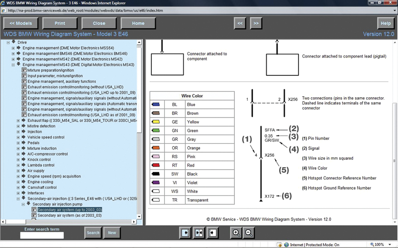
Selecting the “?†box in the lower left gives you a legend of the wiring diagram. Here you can find unfamiliar wire colors and a breakdown of how wiring is to be identified. Also, connector names and pin locations are described.
Within each component you’ll see the circuitry of each wire entering it. From this you can tell if the wiring is power supply, switched power, switched ground, or ground. This is helpful in determining how a circuit functions and what voltage/amperage controls you can expect to see. For instance, looking at a relay you see which wires are for the control coil and which are for the switched circuit. You can put a multi-meter across a control coil and see if it is being activated. You can also install a jumper wire between switched circuits and bypass the relay to test if the component functions. Within control units, you will see the symbol for a power transistor usually connected to ground. This indicates that the wire should get pulled to ground when the computer commands it, such as with a purge solenoid or injector. If monitoring this wire with an oscilloscope, you will see voltage on it get toggled to ground.
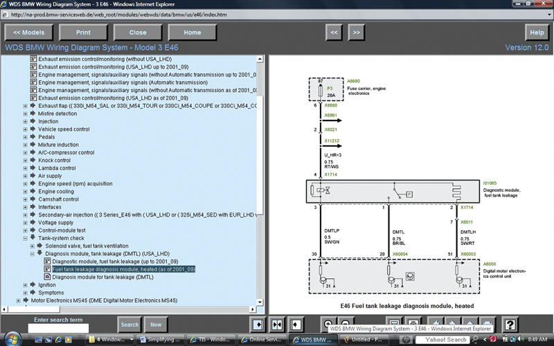
Looking at this wiring diagram of a DMTL system, you see that the black wire with the red tracer has the designation DMTLH. This is the ground for the EVAP system heater. The power transistor inside the DME indicates that this wire is grounded for activation.
Each wire has its own identification tag with symbols that represent what the wire does. The top line of the description is an abbreviation of the function. This can be letters and/or numbers. For instance, while looking at the diagram for Diagnostic Module Tank Leakage, you will see the abbreviation DMTLH with the wire connected to the symbol for a heater element in the DMTL component. This indicates that the wire grounds the heater (the power supply is the same one as for the DMTL pump). The numbers follow DIN standards, so if you see “30” you know the wire is a constant power supply. The number 15 would indicate ignition-on power, Number 31 would be a ground, and so on. Of course, the wire size is indicated in millimeters, and the color markings are there. If there is some question about a symbol or wire color used in the diagram, you can select the “?†in the lower right hand corner of the toolbar. This link takes you to a page with the legend for the diagram, which breaks down the wiring symbols and colors for you. When applicable, you will notice a “text†box below the diagrams on the right side of the screen. This displays a description of system operation. It gives a written account of the circuit’s operation and the overall function of the system. This is helpful on systems you may not have previous experience with.
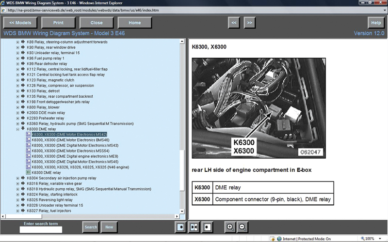
By selecting one of the green links inside the wiring diagram, you will be directed to a pull-down menu in the navigation bar. After selecting the particular variant, you will see the component location of the link you selected. This can make finding fuses, relays and splices easy.
Another feature is the “quick link.†These are the green alpha-numeric designations of component and connector locations. These quick links are found in both the simplified schematics and the more detailed wiring diagrams. Of course, the more detailed diagrams have the quick links for the connectors and splices included. The quick links found in the simplified schematics mainly direct you to component locations. This can prove extremely helpful when locating a fuse within a fuse box, as well as other components. Once you have clicked on a quick link, you will see the navigation page move toward the bottom of the folders where more wiring and component locations are stored. At the top of the list you will see more images.
These pictures display all of the wiring of the component you’ve selected. This way you can follow the wiring diagram of the splice you have just selected. Below these links are blue colored links that take you to photos of component location of the splice you have selected.
In Summation
Taking a look at the proper wiring diagram before the vehicle even gets to the shop will allow you to plan your diagnostic strategy. You’ll also be able to determine which wires should have voltage, what consumers they supply and how these consumers are ground controlled. A good game plan will lead you to an accurate diagnosis, and that’s good for business.


0 Comments