
I was called in to a shop that had a complaint of an illuminated check engine light (MIL) on a 2005 Cadillac Escalade with a 6.0L V8 (Figure 1). The shop was wrestling with an IAT temp code, but was hesitant about changing the MAF sensor due to the low mileage (18,000) on the vehicle. The IAT sensor wiring at the sensor checked out fine, but the shop was still seeing a negative value on the IAT sensor reading on the scan tool. The Intake Air Temp sensor on this vehicle is incorporated within the MAF sensor assembly. Hanging one of these sensors on the engine without any results could prove to be a costly mistake. If you purchase a part and it doesn’t resolve the problem, the wedding ring goes on and you’re now married to the vehicle. It becomes a love/hate relationship with no turning back because you have now committed yourself to fixing the car. You could, however, choose divorce, but that would only lead to you having to eat the unwanted parts and losing the trust of your customer, who may label you as a parts changer.
The IAT sensor itself varies its resistance according to the ambient air temperature it is exposed to. With the negative-coefficient type, its resistance value will increase as temperature decreases. The PCM supplies the IAT sensor with a five-volt reference feed and a reference ground. The resistance of the sensor will rise when it encounters incoming cool air, and it will move the five-volt ref line further away from ground. This can be easily seen if you were to graph an IAT sensor and simply snap the throttle to allow a rush of cool air to enter the MAF sensor housing.
I first scanned the vehicle (Figure 2) and pulled a code P0113. This indicated that the circuit was high above the threshold allowed for the sensor’s range of operation. By also looking at the freeze-frame (Figure 2), you can see that the engine was at an operating temperature of 176 deg. F. when the IAT sensor failed with a reading of -38 deg. F. The freeze’frame information holds a lot of value for a technician by allowing him or her to actually see what events took place at the time of the failure. It’s important for a technician to have a set of parameters to view, such as rpm, coolant temperature, throttle position, air flow rate, fuel trim information, and even vehicle speed. This can provide criteria that may by needed in order to duplicate the problem, especially if it’s not present at the time the vehicle is driven to the shop. There are a lot more freeze frame PIDs available on newer OBD II systems, and this list will only get bigger in the future.
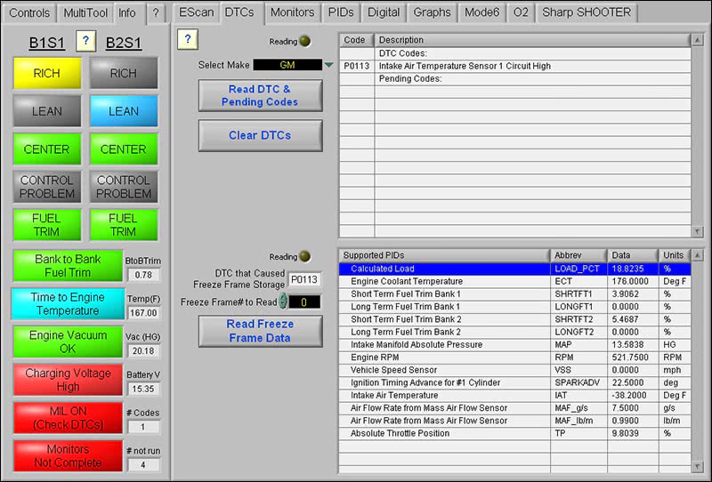
To verify the IAT failure, I selected the IAT parameter in digital format (Figure 3) and I could see the -38 deg. F. value on the scan tool. What was also interesting was that the scanner pointed out that the vehicle was over-charging at 15.3 volts. This can be seen in the left side bar of the screen shot (Figure 3). At this point, I wanted to concentrate only on the IAT temp failure, and deal with the charging system problem later. It is not uncommon for a vehicle to have multiple problems during a visit to a shop. You need to concentrate on fixing one problem at a time, or you will be spreading yourself thin by being all over the diagnostic map. This is unless you feel that certain problems may be related to one root cause creating a chain reaction, such as a misfire code and O2 code created by lean operation due to a bad fuel pump.

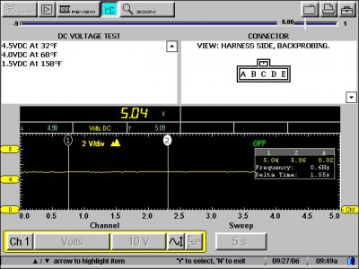
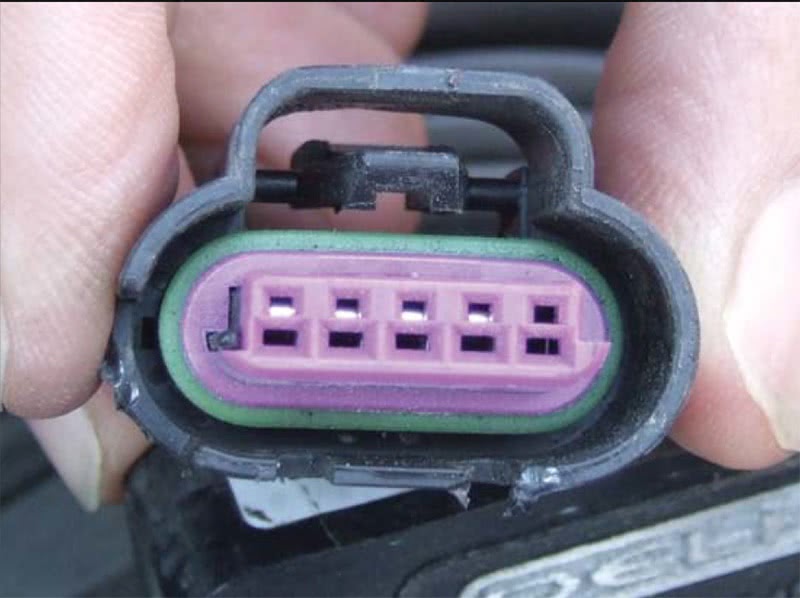
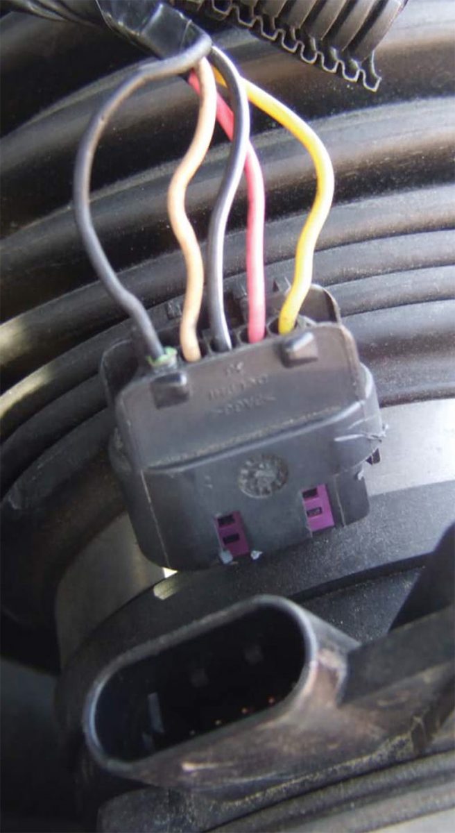
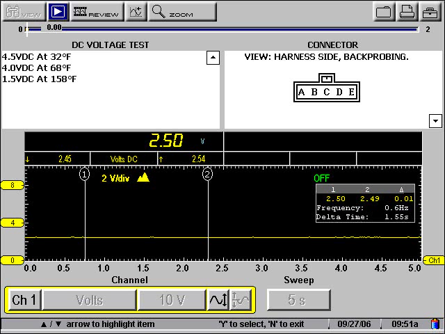
I went back to the IAT sensor connector to take a reading with my component tester and found the IAT sensor line to be at 5V (Figure 4). According to the component tester screen and taking into account the high temperatures within the engine compartment, the IAT value should have been well below 4.0 V. The only way the reference voltage could be at 5V is if the reference ground was bad, or the sensor was on an open circuit. I checked the reference ground at the sensor connector and found it to be well below 100mV, so my next move was to unplug the sensor to check the integrity of the connector. It is not uncommon for a connector to have a collapsed pin, or even a broken stranded wire so it’s only being held together by the insulation. When I pulled the connector (Figure 5) I was surprised to see only four pins showing at the end of the connector. The IAT reference ground had backed out of the connector (Figure 6).
At this point I simply pushed the pin back in place and reinstalled the connector. I took another reading with my component tester (Figure 7) and I could see the IAT sensor value came back down to the proper level of about 2.5V. I erased the codes and started the vehicle up again to view the IAT sensor value, which was now reading about 86 deg. F. (Figure 8). To my surprise, the charging voltage also came back to a normal reading of about 14.66V (Figure 8).
The garage was very relieved to find out that the problem turned out to be a simple fix with no major parts purchased. This is the kind situation where customers would be happy to pay for diagnostic time and the repair of a harness connector knowing that you saved them money on unnecessary parts that could not be returned to the jobber.
The connector pin could have been pulled out when someone was replacing the air filter and inadvertently tugged on the MAF harness connector. It was an unforeseen problem that could be mistaken for a component failure. But let’s get back to the high charging volts of the alternator, and why it was now okay. I gave this one a lot of thought and just applied some logic to the voltage readings I saw on the scan tool. The PCM saw the ambient temperature of -38 deg. F. and decided to up the charging rate of the alternator to keep the electrons within a very cold battery moving. This was a normal reaction of the PCM to counteract the frigid ambient conditions it believed the vehicle was exposed to. Once I repaired the problem, the PCM saw the correct ambient temperature and lowered the charging voltage back to a normal state. If you’ll remember, Chrysler also used the IAT sensor to control charging voltage according to ambient temperature. This is why the company renamed its IAT sensor a “battery temp sensor” and relocated it much closer to the battery.
Gathering information and not jumping to conclusions without checking all the possibilities is crucial to a successful diagnosis. Testing a connector should not just involve external examination by back-probing the wires, but also an integrity check of the mating plug for proper fit, orientation of wiring at the plug, and the wiring strands leading into the connector pins. There are even tool makers who will sell gauge pins to test the fit of a female connector. Don’t be the guy on the outside looking in. Be the guy on the inside looking out as well. I hope this story hits home with a lot of techs out there in the trenches.
by John Anello, “The Auto Tech on Wheels”



0 Comments