We’ve all had to keep pace with rapidly-advancing technology, perhaps especially so with new developments in automotive safety. It seems that every year or so a new airbag gets added — driver’s side, passenger’s side, dual-stage, side, curtain airbag, knee bolster, etc. These measures have reduced fatalities and serious injuries, and their resultant medical costs. But they’ve also been known to kill. Small children and frail elderly people sometimes can’t survive the full force of a deploying airbag. For years, the only defense was to relegate such passengers to the back seat. Now, airbag technology has advanced to the point that occupant detection systems measure the weight of the passenger and determine if and how the airbags should be fired.
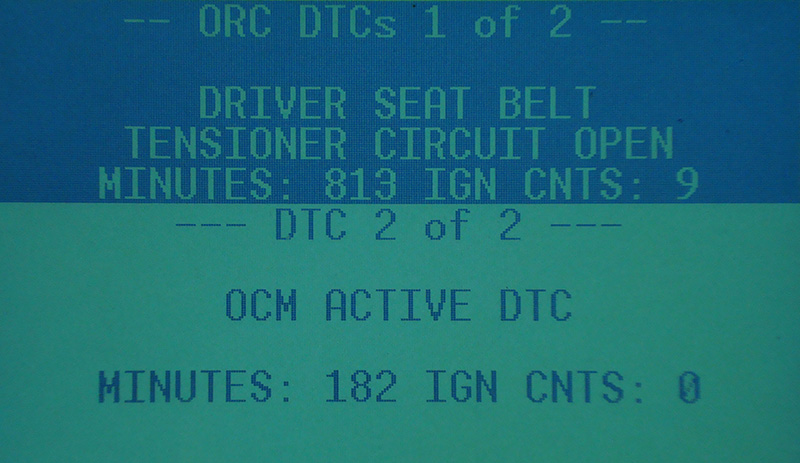
The primary code led us to diagnose a bad seat belt tensioner, but the second code directed us to a relatively item added in 2005, the Occupancy Classification Module.
But what if something goes wrong? In the past, we’ve had to diagnose bad airbag squibs, crash sensors, and clock-springs, but a problem in the detection system was new to us. A 2005 Chrysler Town & Country came in with the airbag light on. While pulling codes, we realized that there are two different systems we can communicate with. On this Town & Country, Chrysler used an ORC (Occupant Restraint Controller — a.k.a. Airbag Control Module), and an OCM (Occupancy Classification Module — a.k.a. Occupant Sensor). In earlier years, the ORC controlled both driver’s and passenger’s side airbags solely on the basis of the seat belt buckle switch status. In 2005, the OCM got input from additional sensors that monitor the passenger’s side front seat.
Since we had a warning light, our first step was to pull codes. We looked in the ORC and found two codes: Driver’s Seat Belt Tensioner Circuit Open, and OCM Active DTCs. On this particular model, the seat belt tensioner is on the buckle side of the belt assembly, not on the adjustable belt side. We then checked for codes in the OCM. Occupant Classification Undetermined Status, No ORC Messages and OCM Data Transfer Error came up. The ORC code for the driver’s side seat belt tensioner circuit was a straightforward diagnosis. Chrysler has a one-ohm resistor tool that you substitute for the tensioner or airbag circuit. You then clear the codes and see if they come back. If they do, you have a wiring or control unit problem. If they don’t, replace the seat belt tensioner.
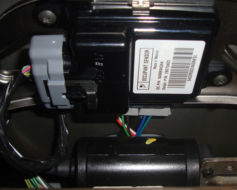
The OCM module is located under the front passenger seat cushion. It gets voltage from the Front Control Module, and relies on both a weight sensor and a seat belt tension sensor to determine how the passenger’s side airbags should be fired.
Of course, before doing any diagnostic or repair work you must disconnect the battery for at least two minutes to be safe. You can then unplug the airbags and tensioners and replace them with the one-ohm load simulator to test for codes. If you don’t have this special tool, you can also check resistance on individual wires between the ORC and, in our case, the driver’s side seat belt tensioner squib. Keep in mind that there are shorting bars in the ORC computer connector. When it’s unplugged the two wires for each squib are shorted together to prevent accidental firing. If you measure resistance between these wiring pairs you should see continuity, which is normal. This vehicle ended up needing the driver’s side seat belt buckle, but we had other fish to fry.
The three codes found in the OCM still turned on the light. These codes all dealt with the passenger’s side airbag system, the heart of which is the OCM module. This module doesn’t fire the airbags, or control the airbag warning light. What it does is monitor if someone is sitting in the passenger side seat and reports this information back to the ORC, which is in charge of deployment. These modules communicate through a single-wire PCI bus. We wanted to verify that this wire was not shorted to power or ground, or open. We checked resistance from pin #15 of the ORC and pin #8 of the OCM and measured just under ¼ of an ohm.
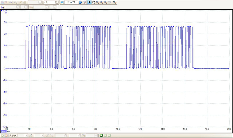
By watching the oscilloscope pattern of the PCI bus we could easily determine that there was communication among control units. The bus links many modules, so it was possible that some other unit was interfering with communications. That should have flagged some other communication code, however.
By putting a lab scope on the communication wire, we could see if there was communication, or if there was interference from other voltage or ground sources. We did see a 7.1 to 7.5V square wave with the ignition key on. This meant the wires were not shorted and the control units could communicate with each other. If there was a communication problem between these two units, it could be because one of the units was malfunctioning, or some other control unit was putting out erroneous data and confusing the others. We decided to check codes in the other control units on the PCI bus, but didn’t find any that dealt with a loss of communication. So, we concluded that the communication problem was isolated between the ORC and the OCM units.
We suspected the OCM module because the first code (Occupant Classification Undetermined Status) suggested that it may not be functioning properly. The second code (No ORC Messages) meant that the OCM could not communicate with the ORC even though we could see the communication on the PCI bus. The final nail in the OCM coffin was the last code — OCM Data Transfer Error. We knew the communication wire was okay, so the OCM itself must have been causing the problem. We wanted to be sure that there were no other outside influences causing the OCM to not work properly. You should always check powers and grounds before replacing any control unit, but with newer CAN systems that can be tricky.
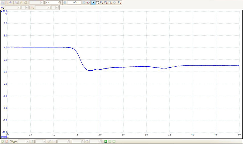
Looking at this weight sensor signal, we see about 4V volts with the ignition key on. The voltage dropped to about 1V with 185lbs in the seat. You can watch this signal voltage with a DMM as well.
This OCM is directly grounded through pin #5. The power supply is another matter — there’s no conventional fuse supplying ignition-on power to the unit. A Front Control Module, incorporated into the Integrated Power Module, supplies almost 11V to pin #9 of the OCM when the ignition key is turned on. Without this power-up signal, the OCM may not communicate with the other control units on the PCI bus. In our case, both the power-up signal and ground passed our tests. To further see if outside influences were causing the OCM to fail, we decided to check the two other sensors that provide inputs to the OCM.
The first is a weight sensor in the bottom of the passenger seat. It is a bladder type sensor with three wires for reference voltage, signal, and ground. The reference is 5V and comes from pin #7. The signal comes in on pin #6 and changes with the weight applied to the seat. With no weight, you should see about 4V, and with a 185 lb. man in the seat the signal drops to just about 1V. In other words, the greater the weight, the lower the signal voltage. If you have codes for this sensor, refer to TSB #08-001-04 on passenger side airbag safety issues and aftermarket parts, such as an add-on cushion, that can interfere with proper sensor operation.
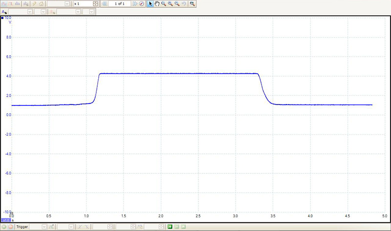
The seat belt tension sensor is mounted in the lower mount of the belt, so moving the reel will not change the signal voltage. You can check the voltage and pull up on the belt. You should see the signal voltage change from about 1V to 4.3V while pulling.
The second is the Belt Tension Sensor. This component also uses a three-wire design. The 5V reference comes from pin #16 of the OCM, and isn’t shared with that of the weight sensor. The ground is also separate and comes through pin #14. The belt tension signal comes in on pin #4. With no tension on the belt, you should see just under 1V on the signal line. Pulling the belt out of the B-pillar mount will not cause the signal to change. The sensor reads the tension on the mount side at the base of the B-pillar. Grab the belt near the base and pull up. You should see the signal rise to about 4.3V.
Since the sensors were functioning properly, our repair was going to be the installation of a new OCM. It’s mounted on the underside of the passenger seat cushion, and is fairly easy to get to. Even though it’s a control unit, it doesn’t need to be programmed or coded when installed. However, it is not just plug-and-play, either. You will have to calibrate the weight sensor after installing a new OCM. With your DRB III/Star Scan, or equivalent, you can calibrate the weight sensor, but you are going to have to throw some weight around. It is a three-stage process. You start with an empty seat. You then put 37.5 lbs. on the seat. In the next step you add an additional 10.6 lbs., and, finally, 52.5 lbs.
With a total of five codes in this Chrysler airbag system, we needed to make the customer aware of the hours of diagnostic time that would be needed to be accurate and precise with our conclusions. We must be bold enough to ask for an honest amount of diagnostic time so we don’t paint ourselves in a corner. During that time we need to perform all of the testing we can so we can make come to an educated conclusion. We know. With all the new systems springing up these days, that’s easier said than done.
by Kerry Jonsson


0 Comments