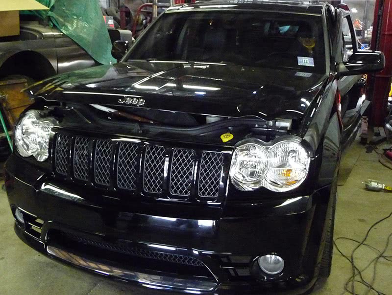
I was called to a shop to program a new Powertrain Control Module on a 2007 Jeep Grand Cherokee (Figure 1). The shop diagnosed the Jeep and made the decision to purchase a new PCM to resolve a no-start situation. Reprogramming has become a common practice for me these days because a lot of shops do not want to get involved with the procedure. It may be due to costly subscription fees or just the liabilities involved when programming a controller. If you don’t know what you’re doing, or are just not careful enough you could be the proud owner of a new or rebuilt computer. So, sometimes it may be easier for a shop owner to hire my company for these services.
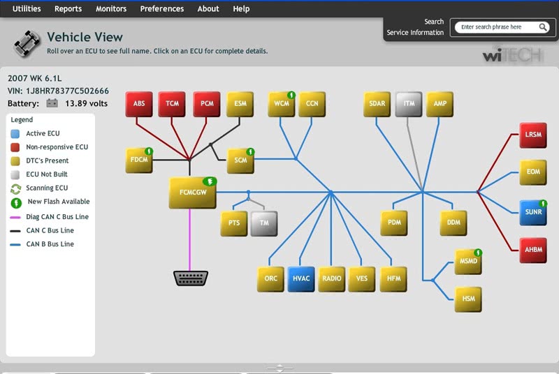
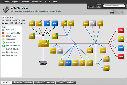
Figure 3: Topology view of onboard controller using the Chrysler WiTech softwareTopology view of onboard controller using the Chrysler WiTech software
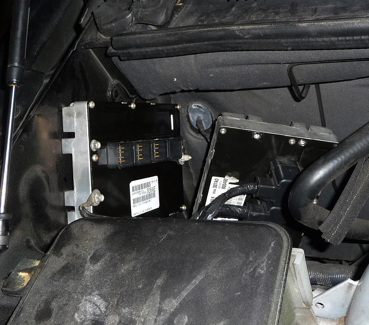
I arrived at the shop and plugged in the old contoller first to read software information about the module so that I could select the proper software I needed on the Chysler website (Figure 2). I placed my Chysler StarMobile interface on the truck and booted up the WiTech software program to “topology” view with the vehicle online with Chrysler’s website. This view is live and provides a lot of information for the working technician with just with one glance at the screen. The controllers are all grouped by different types of networks. Blue lines indicating CAN B, black lines indicating CAN C, gray lines indicating a path to a controller that is not actually on the car, and red lines indicating a dead link to an inoperative controller (Figure 3).You will also notice that any controllers with codes are highlighted in yellow and without codes in blue. If any controllers are in red, they are considered inoperative and off the network. If you look closely, you can see a small green lightning bolt icon on certain controllers indicating that a flash file is available. This is the way a scan tool should be built to really make things easier for the technician.
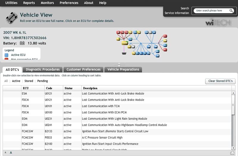
The topology view showed that the PCM was inoperative and I could not communicate with it. The shop techs had the same problem when they hooked up their scan tool, so after performing some checks on the vehicle they determined that the PCM had internal issues. I plugged in the new controller and it didn’t respond, either. The shop had also plugged in the new PCM, but they thought it had to be programmed before it would communicate. I explained to them that even though no software is loaded in the new PCM, it still had a boot file in it to allow it to communicate with the scan tool. There was no way I could do the programming without communication with the PCM. When I minimized the topology screen to view the codes below it, there were a lot of “U” codes stored in other controllers in the network because of the PCM failure (Figure 4). The shop had made a bad decision to condemn the old PCM for not communicating with their scan tool. This vehicle had a wiring problem and I would have to pull some diagrams to power-flow system operation prior to my diagnosis.
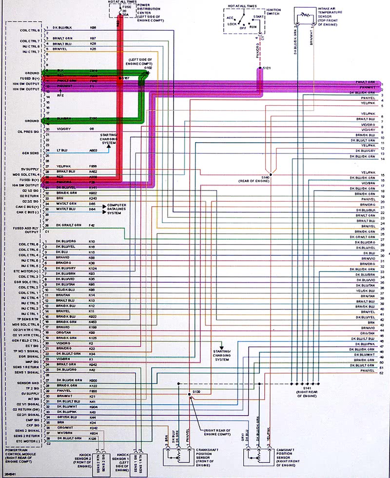
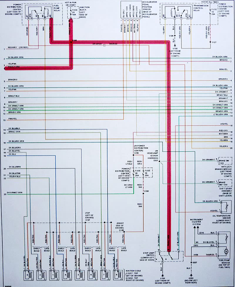
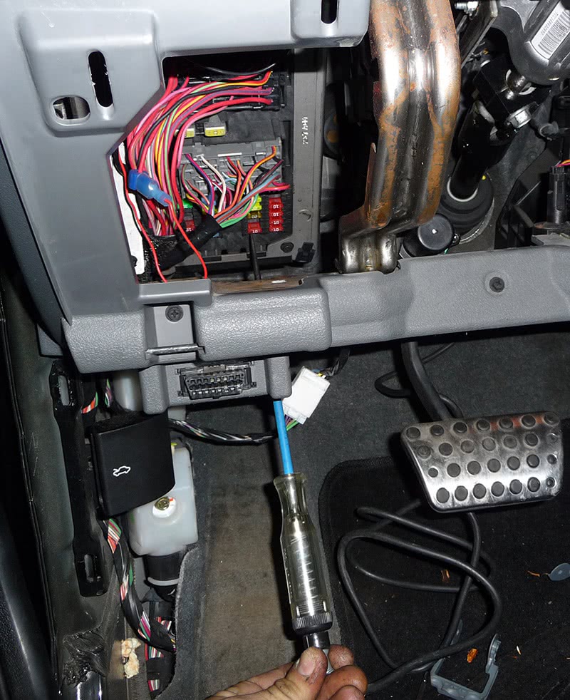
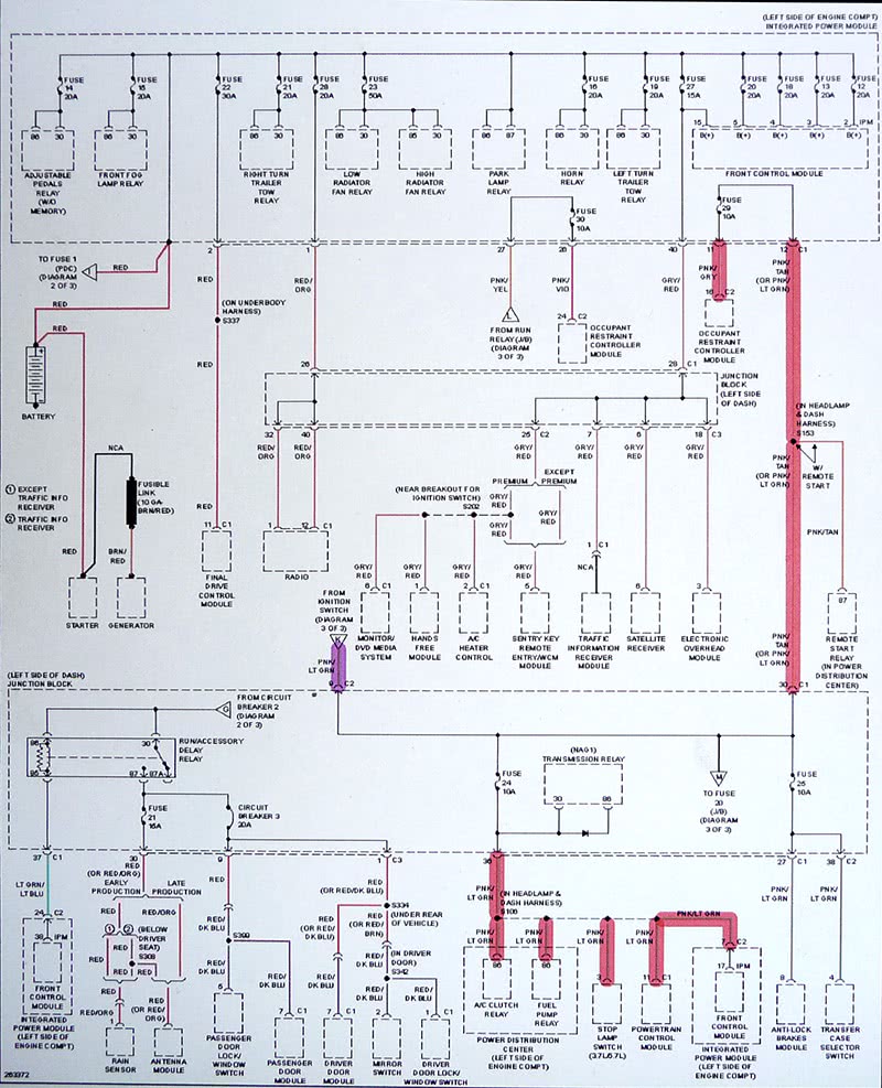
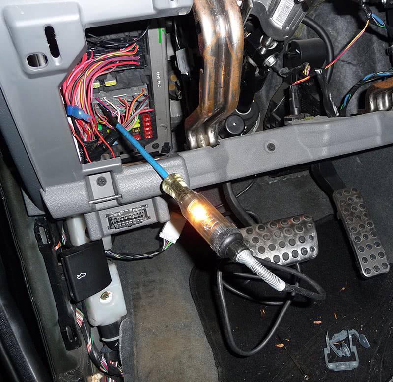
I used Mitchell On Demand to pull a diagram of the PCM (Figure 5). I color-coded the grounds at terminals #9 and # 18 with green , battery feeds at terminals #10 and #29 with red, and ignition feed at terminal #11 with purple. This coloring process makes it easier to read a diagram by isolating the circuits you need to check and mentally flows circuit operation so that you grasp it better. I backprobed the PCM terminals with a test light and found that there was no ignition feed at terminal #11. I printed out another diagram (Figure 6) and followed the ignition feed circuit back to Fuse #24 located in the junction box at the left side of the lower dash. I checked the fuse with a test light and there was no power on either side of the fuse with the key on (Figure 7). I now needed to find out how fuse #24 got its power, so I next printed out another diagram (Figure 8) and followed the #24 fuse feed all the way back to terminal #9 of the C2 connector within the fuse panel housing highlighted in purple.
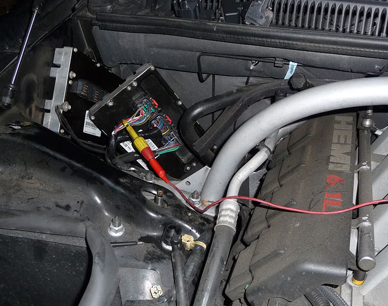
I placed my test light on the #9 terminal pin at the C2 connector of the left side junction box and found that the ignition feed going into the panel was okay (Figure 9). The culprit was a bad fuse panel with an open internal feed circuit. The fix here was to replace the entire fuse panel. At this point the only choice I had was to run a temporary feed line to the PCM to validate my findings to see if the car would run and to make sure there weren’t any more problems at hand. I jumped out the ignition feed to the PCM with a power source (Figure 10) and the car started and ran fine. I then finalized the diagnosis and went back to my topology view to do a health status on the system (Figute 11). I could now see that the TCM and the ABS modules were also up and running because they most likely shared the same ignition feed that was missing. I could also see that there are flash files available for the PCM and the TCM if the owner of the vehicle decides to do some upgrades.
So, the car was running and there was no need for the new PCM that the shop purchased. Parts suppliers usually won’t take back an electrical part, so now the shop owner faced an ethical dilemma. Should he be honest, eat the unnecessary expense and chalk it up to a learning experience? Or, should he have me program the new control unit and bury the whole mess without the owner of the vehicle ever knowing what happened? After all, the customer only wants to see the car running no matter what it takes. I know we’ve all been there, and it is definitely a test of character. How well will your conscience let you sleep at night?
The lesson here is that while the occasional PCM will fail, it behooves you to be absolutely certain that everything it needs to function is available before you spring for the expense of replacing it. I hope this one hits home with a lot of my readers to always take step back in your diagnostics and make sure you’re seeing the big picture.
by John Anello, “The Auto Tech on Wheels”



0 Comments