
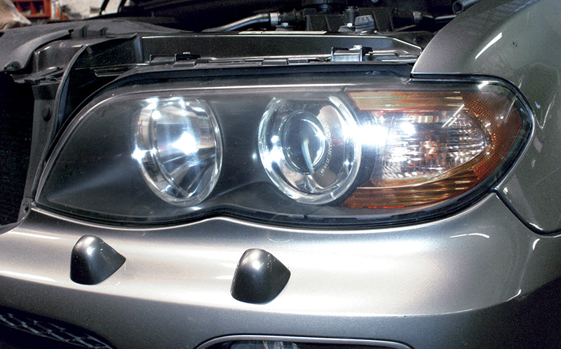
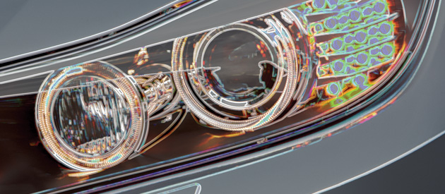
Look at the shape of the lens and you will see a smaller lens within a larger one. This tells us that these are HID Xenon headlights. If a headlight is inoperative, be sure to check bulbs and fuses before looking into more involved components, such as control units.
BMW has made many improvements in all of its safety systems over the years, including three-point seat belts, crumple zones and, of course, Supplemental Inflatable Restraints (Air bags). These are all incredible systems that react to impacts within milliseconds . Three-point seat belts have proved to be the most effective and convenient means of keeping the passengers safely seated upright. Crumple zones absorb significant amounts of energy from the impact, maintaining a protective cocoon around the passenger compartment. Supplemental Inflatable Restraints gradually decelerate the body during severe impacts. All of these components and systems result in a vehicle that is safer for all occupants. Some of these technologies are passive, like crumple zones and air bags, and some, like seat belts, require action on the part of the occupant. But all of them make BMWs some of the safest vehicles on the road.
Of course, the best accident is no accident at all. So, BMW empowers drivers with precision handling, a well-balanced machine, and superior braking to enable them to take aggressive evasive action when necessary. This proactive approach to promoting accident avoidance involves giving drivers the proper tools so they can get themselves out of harm’s way.
But even more essential is the ability of a driver to see what’s ahead in time to deal with it even at high speeds. One of the many ways this is accomplished is with intelligent headlight systems. Conventional headlights do not shed enough light as the vehicle climbs and descends hills, and motors around corners. Recent advancements such as Xenon bulbs, focused beams, and vertical directional headlights all offer a clearer view of the road ahead, especially while cresting hills and rounding corners. All we have to do is keep these systems working.
Turn On The Lights
Starting in the late ‘90s BMW introduced advanced controls for vehicles with Xenon headlights. These intelligent headlights do more than provide light. They also control two aspects of the beam. One is the “throw†or focus of the light beam, and the second is the “height†or vertical angle relative to the road. Both features allow you to see farther down the road. To diagnose and repair this system you need to be familiar with all of the components involved, including the beam’s height control, which is optional.
The Brains
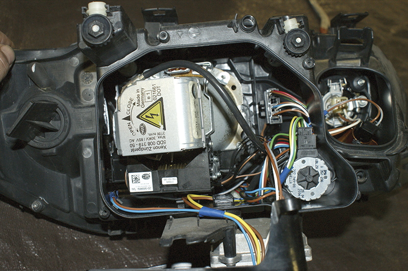
Take a look at the back of a headlight unit with the covers removed and you can see all of the components. On this Gen III assembly, the unit on the bulb is the igniter. Just below it is the non-serviceable beam focus motor. The round motor to the right is the serviceable vertical motor.
The brain of the system is the lighting module. On early versions, the module receives inputs from the various light switches and, in most cases, supplies power directly to individual bulbs. The light switch is not the only input, though. The brake, hazard, turn signal, fog lamp and high beam switches also send signals. Even the interior light dimmer is attached to the lighting module. The sole exception is the reverse light switch input. This signal goes directly to the instrument cluster and is then passed on to the lighting module through the I-Bus. The K-Bus also sends signal inputs to the lighting module for various functions.
The lighting module is in control of all exterior lamps including low beams, high beams, parking or tail lights, brake lights with high-mounted stop lamp, marker lamps, fog lamps, license plate lamps, and reverse lights. The lighting module also controls the instrument cluster lighting by receiving signals from the dimmer switch and providing variable voltage to the instrument panel for illumination. This function also controls the interior lights for switch illumination. The GEM (General Electric Module) is in control of all the other interior lights. For instrument cluster-mounted indicator lights, such as turn signal and hazard indicators, the cluster supplies the power and ground. The instrument cluster receives commands for these various lighting functions through the I-bus from the lighting module.
The lighting module can determine if a bulb is out. It informs the instrument cluster, and the appropriate failure message is displayed to warn the driver. Keep in mind, since not every vehicle has fog lights, the lighting control module is coded for the specific vehicle in which it is installed . When replacing a lighting module you must code it to the vehicle with iComm through BMW’s website www.bmwtechinfo.com. You can upload the existing coding from the old module and download it to the new one. Or, if you cannot communicate with the old lighting module, you can select which features to turn on individually, but you will need to know what options the vehicle came with. If, after replacing the module, you find that some features do not work, it could be because the lighting module has not been coded properly.
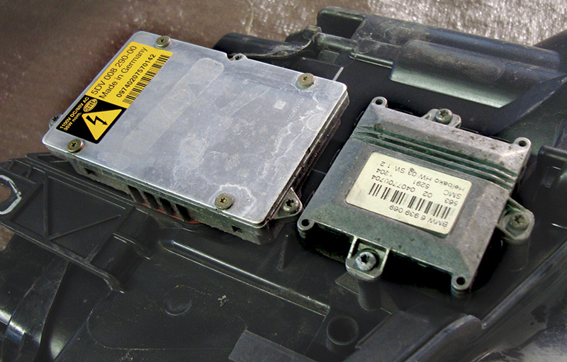
On the underside of this Gen III system you can see two control units. The larger one is the Xenon control unit for lighting. The smaller unit is the widening control module for headlight focus control and aiming.
Are Others Involved?
With BMW’s sophisticated lighting systems comes added complexity. The additional features are headlight widening (referred to as LWR) and Electronic Height Control (referred to as EHC). There is a single headlight widening module controlling both features for both headlight assemblies.. The headlight widening control module is connected to the instrument cluster through the K-Bus. It is discretely wired to the lighting control module so it knows when the headlights are on. An additional discrete input is a speed sensor signal. The control unit monitors inputs from both the lighting module and K-Bus lines and varies output signals accordingly. Since a control unit is in charge of these lighting features, self-diagnostic functions are available, but remember that the lights have to be on while connecting your iComm or a generic equivalent.
Headlight beam width (range) and level position are determined by the headlight-on command, and vehicle attitude, and speed. As we mentioned earlier, the lighting module sends power to the headlight widening control unit. Once powered up, the unit looks directly at the level sensors. One sensor is mounted on the front suspension link and one is mounted on the rear suspension link. From these sensors the headlight widening control unit can determine if the headlights are pointing towards the sky on an ascent, or down at the ground on a descent. The vehicle speed input is another discretely-wired input to the control unit from the ASB/DSC control unit. Typically, one speed sensor, which is usually located at the passenger’s side front wheel, is the speed signal sent out of the ABS/DSC and used for the vehicle speed input.
Now let’s look at some outputs. The level and focus of the headlight beams are all controlled by stepper motors. These stepper motors are directly controlled by the module. They are four-wire motors. Two wires make up one coil, and the other two are for the second coil. One stepper motor controls the focus of the beam and the other controls the height of the beam. Stepper motors offer very small adjustment increments so there is precise control of the focus and level of the beams. Both left and right stepper motors are controlled together. To ensure that they are properly synchronized, they are commanded from one stop to the other every time the key and the headlights are turned on. These stepper motors are mounted in the headlight assembly, so they are not easily seen. The vertical adjustment stepper motor is serviceable, but the focus control motor is not. So, if your diagnosis shows that the focus control motor is faulty, you will have to replace the entire headlight assembly. In newer Gen III systems the stepper motors for focus are controlled directly by the widening control module. On vehicles with the “Automatic†feature, such as the 2003 X5 (E53 chassis), the lighting module controls the beam’s focus.
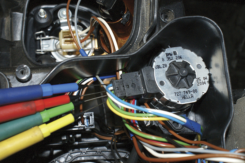
You can monitor the command to the stepper motor while starting the engine and turning on the headlights. While it is nice to scope all four commands at once, you can also monitor each motor command individually with a DMM.
To Be Or Not To Be . . .with Xenon Headlights
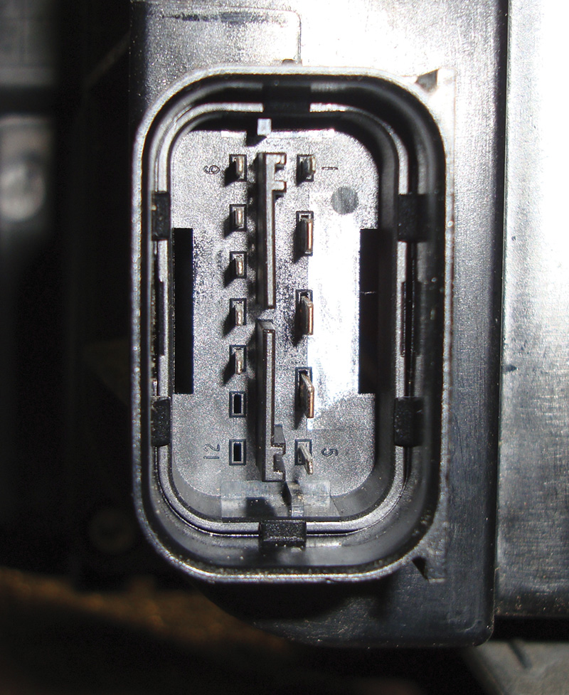
While you may not have all of the factory cables needed to test the assembly, you can still monitor the power supply voltage and ground to the control units at the headlight assembly connector. Simple checks like these are often overlooked, yet can provide the needed solution.
BMW started offering Xenon (HID) headlights on the 750iL (E32 chassis) in the 1993 model year. Of course, the lighting control module is in charge of turning the lights on, but the signal is sent first to the Xenon headlight control unit, which directly powers up the bulb. It is difficult and unsafe to test voltages directly at the Xenon bulb. The voltage spikes to between 18,000 and 25,000 volts to jump across the gap in the bulb. DMMs (Digital Multi-Meters) and their test leads cannot handle voltages that high. There are high-voltage probes for conventional meters that are commercially available that can handle up to 40kV, but this type of testing is not recommended.
For the early Generation 1 HID units ending in the late ‘90s there is a specific cable to be used with the GT1’s measurement system. Generation III uses a different cable and you can use an inductive ammeter to measure the current draw of the system. Since you may not have these tools available, you are limited to testing power supply and ground circuits at the headlight assemblies. However, you can scope the stepper motor control wires inside the headlight housing.
In Conclusion
Just knowing how something works is half the battle. Many of the inputs can be monitored with an iComm or aftermarket equivalent. The outputs can be bi-directionally controlled as well. With a combination of scan tool and electrical testing you should be able to keep most repairs accurate and profitable. â—

0 Comments