
One of the many sterling characteristics of BMW vehicles is their fuel efficiency. Other European luxury manufacturers are only now following BMW’s lead with engines that are both powerful and fuel efficient. Many BMW models already get close to 30 miles to the gallon with normal driving. In order to get the best mpg and still maintain performance and drivability, the DME control unit carefully meters the precise amount of fuel needed for conditions. When everything is working properly, the engines sip fuel and provide the necessary power when the need arises. However, as components wear and tear with normal driving gaskets will dry up, contaminated fuel will clog injector screens and dirty air filters will restrict airflow. All of these conditions and more can lead to mixture problems. The sophisticated electronics of the DME can pick up these mixture irregularities, flag a diagnostic trouble code (DTC) and turn on the check engine light (CEL). These fuel mixture related problems can lead to more severe symptoms such as misfires depending on the extent of the problem. The DME’s sophisticated electronics will shut down misfiring injectors if it is determined it is a catalyst damaging misfire. We are going to need to learn how diagnose if the misfire is caused by a fuel mixture problem.
The Basics of Fuel Control
The basic combustion process starts with an optimal fuel mixture. This optimal mixture is determined by the various sensor inputs to the DME. The base pulse width is typically determined by the two important sensors, the engine position sensors and the engine load sensor. The DME gets the information on engine position from a combination of the crankshaft position sensor and cam position sensor(s). With modern sequentially grounded injectors cam position sensors can verify when the piston is coming up on the compression stroke or coming up on exhaust stroke. This is how the DME determines when the injector is fired. The DME determines how long the injector is opened using the load sensor. The Mass Airflow Sensor (MAF) is the load sensor and measures how much air is being drawn into the intake manifold. Current Catalytic Converters work best with a mixture ratio of 14.7:1 air to fuel. This allows the converter to store oxygen when the mixture is lean and release it when the mixture turns rich. It is the job of the oxygen sensor to sense the oxygen content of the exhaust gas and pass this information along to the DME. If the exhaust gas reads too lean the injector on time will be increased. If the mixture is too rich then the on time will be reduced.
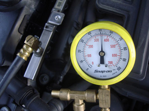
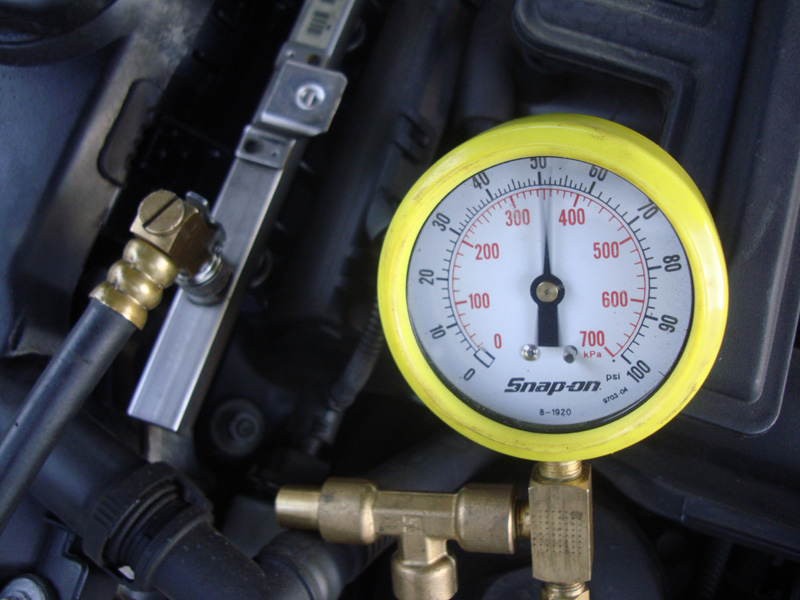
In order for any engine to run properly, it needs sufficient fuel pressure and volume. Here, we are reading approximately 50psi on a vehicle that performs well. Under hard acceleration, this reading must not drop. If it does, there’s a problem with fuel volume. Check for a clogged filter before changing the fuel pump.
Older BMWs use single wire and 4 wire O2 sensors. These are typical zirconia type sensors that have a two heater wires, one power and one ground, an O2 sensor ground and the signal wire. The signal wire can range between .01 of a volt to .5 of a volt to indicate a lean condition and .5 to 1.0 volt to indicate a rich condition. We can easily measure this with a voltmeter as well as observe the voltage change on our iComm scan tool with ISTA or equivalent. In later years a slightly different NGK linear planar titania type sensor is used. This sensor works the same way as a conventional O2 sensor but a 5 volt reference is supplied by the PCM. The sensor toggles the 5 volt reference depending on the mixture in the exhaust. With this sensor 0 to 2.5 volts indicates a rich condition and 2.5 to 5.0 volts indicates a lean condition, which is the opposite of the zirconia type sensor. Instead of this type of sensor switching above and below .5 of a volt the titania sensor switches above and below 2.5 volts as it bounces between a lean and a rich condition.
Late model BMWs use the latest in oxygen sensor technology. The latest sensor is referred to as an air/fuel ratio sensor. Its operation is significantly different from the previous zirconia and titania type sensor in that the voltage no longer indicates a rich or lean condition. Sophisticated electronics use milliamps (ma) to indicate a rich or lean condition. The basic operation of the air/fuel ratio sensor is this. As the mixture passes by the sensor it is drawn into a chamber within the air/fuel ratio sensor. If it is a lean condition more current (ma) is pumped into the sensor through a pump cell from the DME to draw in a greater amount of the exhaust gas. The more current has to be pumped in the leaner the mixture. If the mixture is rich current is taken away from the pump cell by the DME. The greater the current is taken away the richer the mixture is. Although the sensor operation is complicated it is also capable of accurately reading mixtures as low as 22:1 air to fuel, something a zirconia or titania sensor cannot do accurately. These sensors do require greater heater control from the DME since they need to work at a much higher temperature but they can start working in closed loop much faster than older O2 sensor designs, usually within 30 seconds of starting the engine.
The Air/Fuel Ratio Sensor
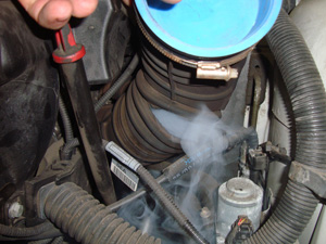
An air intake leak can lead to symptoms similar to those of a traditional vacuum leak. Here, the intake manifold is not leaking, but a rip in the air intake duct is allowing air to enter the intake without being measured by the MAF (called “false airâ€). The low reading of the MAF will skew the amount of fuel injected into the engine downward, resulting in an overly lean condition. The motion of engine torque may open the crack wider making the problem worse.
This allows the mixture to be monitored and controlled during the engine warm up period and can reduce emissions significantly during this period. Since the sensor works by pumping milliamps back and forth between the sensor and the DME it is difficult to determine a rich or lean condition with a ammeter. The signal amperage may only toggle between -20 to +20ma. Also when measuring amperage you need to connect you meter in series. The measured current needs to pass through the meter. This means you will need to open the circuit to install your meter. This type of testing can be time consuming and is not cost effective. There are other ways of testing the air/fuel ratio sensor and diagnosing mixture related problems. The iComm/ISTA diagnostic system does allow you to monitor the activity of the air/fuel ratio sensor and all of the sensors that affect the desired fuel mixture. It can also provide this information throughout the entire rev range of the engine. This is significant because a mixture related problem at idle can have a totally different cause than a mixture related problem at 3000rpm. What tools are at our disposal to isolate the cause of the mixture problem?
We tend to have the bad habit of immediately pulling out our scan tool and start looking for electronic fuel injection problems when we have a drivability problem or DTCs. As with any automotive system the basics have to be checked first before we can go on to more sophisticated testing. With mixture related codes this is no different. Before an engine can function the way it is designed it needs to have proper engine timing, sufficient spark and the correct fuel supply. The BMW DME is a pretty smart computer and can watch the crankshaft and camshaft position sensors to determine if the valve timing is off. You can also put a lab scope on the crank and cam position sensors and compare the pattern you get with a known good running vehicle. If you suspect a spark problem first look at the spark plugs. If they are worn they usually lead to a slightly rich condition. Severe wear can lead to misfires. To be sure you are installing the correct plug it is a good idea to purchase them from your BMW dealer. The coils should fire and HEI spark tester. You can always evaluate the ignition pattern on your ignition scope if you have a suitable adapter for the ignition coil.
Mixture Adaptation
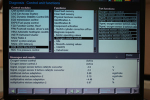
Using your GT1 software, you can see the additive and multiplicative readings in real time. As you can see here, Bank 1 has a severe problem with fuel mixture in both the additive and multiplicative rpm ranges. The .68 mg/stroke means it is adding fuel at idle. The negative multiplicative fuel trim reading of -4.48% means it is rich and subtracting fuel at part throttle.
A greater concern with fuel mixture codes are the fuel and air supplies. These are the most common faults when it comes to mixture related codes that do not lead to a drivability problem. Plus or minus 10% on the mixture scale will set a code but may not necessarily to a drivability problem. These are often the harder problems to find since the fault is so subtle. For these problems our iComm/ISTA scan tool is ideal. It can read the data provided in real time by the DME. Most European manufacturers, BMW included, do not use the same long term/short term fuel trim scale that Domestic and Asian manufacturers do. You can retrieve this information using Generic OBD – II scan tool communication but long and short term fuel trims only tell you if the problem has been going on for a while. BMW data gives the mixture information in “Additive†and “Multiplicative†scales. These scales tell you in real time what the mixture is doing at the moment. The additive fuel scale tells you the fuel trim correction factor at idle and just above idle. The multiplicative fuel scale gives you the fuel trim correction factor above idle and in the higher rpm ranges. This is an excellent way to determine when the vehicle is having the problem and where you should test it.
If the problem shows up with high numbers on the additive fuel trim you should test the vehicle at idle and see what can affect the mixture under idle conditions. You should also look at the same time the multiplicative fuel trim and compare them to the additive readings. Look at the definition of the specific code you have. It will indicate if the problem is in the additive or multiplicative rpm ranges or both. The scales may be different for both readings. BMW generally gives the additive reading in milliseconds of injector pulse width or milligrams per stroke. A positive number means the vehicle is lean and trying to open the injector longer to add fuel. A negative number means the engine sees a rich condition and is reducing injector pulse. The increments are very small, but if you see a significant change compared to a good running vehicle, you’ve found out something. The same rules apply to the multiplicative scale except it is usually displayed in terms of “Lambda†or 100%. Above 1.00 (Lambda) or above 100% the engine is lean and the computer feels it needs to add fuel. Below 1.00 or 100% the DME sees a rich condition and is reducing injector on time. Carefully examining these numbers can lead you to the correct tests you should perform.
Looking For Clues
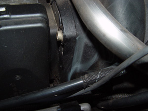
Pumping smoke into the intake is a great way to verify a vacuum leak. This one is at the front throttle plate adapter of a V8 engine and verifies that the gasket needs to be replaced. This type of leak will lead to higher additive trim readings, but will not have much of an effect on multiplicative readings.
As an example if your additive correction factor is positive and relatively high but the multiplicative is normal your problem is a lean condition at idle. You should check the fuel pressure of the supply system and make sure fuel pressure is not too low. It probably isn’t because if fuel pressure was low you would also have low fuel pressure at high rpm and flag a code for multiplicative fuel control as well. If the problem is only at idle then you either have too little fuel or too much air only at idle. Take a quick peak at the idle speed correction factor. If the DME is reading negative numbers then it is trying to close the idle speed motor. Many BMWs that have electronic throttle still retain the idle speed motor. This means there is extra air getting into the intake and keeping the idle speed too high. At this point connect your smoke machine and start looking for a vacuum leak leaning out the mixture at idle. A small vacuum leak may affect the fuel trim at idle but does not pass enough air to affect the fuel mixture at higher rpm ranges. What if the scenario is reversed?
What if the additive fuel trim is normal but the multiplicative fuel trim is high. On a scale of 1.00 the reading 1.10 would be equivalent to 10% fuel correction. This will flag a code. We can conclude it is probably not a vacuum leak since there is no problem at idle. But the mixture is being leaned out at part throttle. At higher rpm we have either too much air or not enough fuel. At higher rpm fuel pressure and volume need to be looked at. A fuel volume tester is the best way to insure proper volume with higher loads. Many newer BMWs have returnless fuel system where the fuel pressure regulator is incorporated in the fuel filter or in the fuel pump module assembly. In these cases we cannot block the return line to check the fuel pump’s maximum output. You can watch fuel pressure under hard acceleration but you should have someone else drive the vehicle to maintain road safety. The fuel pressure should not drop under acceleration. If fuel volume is a problem it can lead to a lean condition and will flag a code in the multiplicative range. Pushing the button on your fuel pressure tester is a crude way to verifying sufficient fuel supply and you should refrain from doing so.
The Usual Suspects
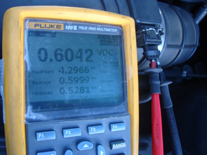
You can measure MAF signal voltage directly with a DMM. Here, we see with the engine at idle that the MAF is putting out .6V. Using the MAX/MIN feature of the meter, we see the peak signal voltage reached is just about 4.3V under hard acceleration, not a terrible reading for a MAF.
Another concern with lean multiplicative conditions is the MAF. As mentioned earlier the MAF or load sensor makes up the base pulse width. If oil or dirt contaminated MAF cannot measure the exact amount of air being drawn into the engine the DME will not open the injectors for the proper amount of time resulting in the lean condition. Less measured air means less measured fuel. If the fuel supply is sufficient you should then check the MAF sensors responsiveness. This can be done with a Digital Volt Ohm Meter (DVOM) either by measuring an analogue voltage or frequency. As an example older MAFs would read just about 4.0 volts under hard acceleration. Once again have someone else driving to maintain road safety. More modern MAFs as found on a E46 chassis with the 330i straight six can almost reach 4.5 volts on a snap throttle. A dirty MAF will read less than these so you can attempt to clean it and see if the readings changes. If it does replace the MAF as cleaning is only a temporary solution to the problem. Remember a MAF will affect the fuel trims on both banks. Even on a six cylinder the first three cylinders are considered bank 1 and 4 thru 6 are bank 2. If you only have mixture codes on one bank check for a specific vacuum leak, clogged injector(s) and/or a malfunctioning O2/air/fuel ratio sensor.
By mid-2000 and later model MAF’s send out the signal as a frequency reading. This is a change from the earlier analog voltage reading in the past. With an analog MAF the voltage reading increases proportional to airflow. On the newer digital MAF the voltage and the duty cycle of the square-wave stay the same only the frequency (pulses per second) increases in proportion with airflow. You can still use additive and multiplicative readings to assist in the diagnosis of the mixture control problem. When dealing with fuel mixture codes you need to test all of the factors involved in correcting the mixture. Understand MAF and fuel pressure/volume problems will affect both bank equally. Intake runner vacuum leaks and oxygen sensor/air/fuel ratio sensors usually affect only the bank they are installed in. Use your additive and multiplicative readings to isolate the problem and verify the solution with component specific testing. Your customers will be happy the problem is completely repaired and your will be happy when they do not come back with the same problem. Good job guys.


0 Comments