
One of the most frequently-used accessories on any vehicle is power windows. They are installed on virtually every car sold in the United States. Older, less complicated systems only had a simple switch to complete the circuit to the window motor. Now, we have modern features such as “one-touch†where with a simple push of a button the window will go all the way down by itself, which is especially convenient when approaching a toll booth. In later-model BMWs, we have the ultra-modern “convenience†feature. This allows you to automatically open or close all windows by operating the door lock system. Simply hold the key in the lock position and all of the windows (and sunroof) will close. This is great when one of the children has left a window open after you shut the car off. By holding the door lock cylinder in the unlock position you can open all the windows before you get it. In the summer, this is a great way to let the hot air out of the cabin. These modern conveniences come at the price of added complexity, however. But, an accurate and cost-effective diagnosis is still possible if you are familiar with the way the system is wired and how it works.
Way back
You can go back as far as the E32/2 chassis to see when BMW started to implement computer controls of the power windows. Starting as early as the 1988 BMW 7-Series, a computer called the General Module (GM) was in control of all power window functions. The system was slightly more complicated than what you are probably familiar with. As in any computerized system, the main control unit receives input and manipulates various outputs according to its programming. In this case, the E32/2 driver’s door switch does not send power and ground directly to the window motor to move the window up or down. Each door switch provides a two-wire input to the GM. In the up position one wire is going to ground, and in the down position the second wire is going to ground. The GM sees which wire is commanded to ground and responds by opening or closing the appropriate window. It does this by operating a relay module, which is what actually provides the power and ground for each window motor.
Through the early ‘90s, the 5-Series had the same type of power window control with a GM, switch input, and a relay module, while models such as the E30 3-Series had different systems. Two-door models had individual control units in each door. A solid-state controller had built-in relays to handle the power and ground supply to the window motor. On four-door models, only the driver’s door is computer-controlled (the others use manual switches). These is a rudimentary computer that is built into the window motor assembly. The door switch inputs are simply reference voltages that get toggled to ground to command the window open or closed. The door control modules also have Hall-effect sensors built into the motor so the control unit knows the window’s position.
Although these systems had control units, they did not have scan tool diagnostic capability yet. For diagnostics, you have to go to each control unit and check voltage on each of the pins until you identified the problem. This, of course, would change in later years with more sophisticated systems.
In ’94, the 3-Series received the same architecture as the earlier 5-Series with one notable exception: The rear windows are controlled by a relay module and only have one-touch operation in the down direction. With the front widows, one-touch operation tells the ZKE IV control unit to move the window all the way down, or all the way up. With conventional thinking up to this point, it would take at least five wires to make this happen. You would need at least one ground, and four different wires to indicate each option of up, down, one-touch up, and one-touch down. If you want to illuminate a switch, that would make for an additional wire. To reduce the number of wires, the ZKE IV uses switch logic to figure out the command. Using only two wires, it can determine which of the four different options the occupant wants performed. The way the switch is wired, if one wire goes to ground the window either opens or closes. If both wires go to ground, then one-touch operation is selected.
The ZKE IV control unit needs to know the position of the window motor at that moment in order to execute the correct command. With both wires going to ground at or near the same time how does the unit know in which direction to operate the window motor? If it knows the position of the motor, then it can figure out to close an open window and open a closed one. A three-wire Hall-effect sensor is built into each motor, and the ZKE IV uses their signals to determine window position. In the case of a disconnected battery or a replaced window motor, the control unit may “forget†or lose track of the window position, so a procedure needs to be followed to allow the ZKE IV to learn the window positions again. It is usually a simple procedure of moving the window all the way down and continue to hold the switch down for five seconds after the window has stopped. Then, you move the window to the up position and hold it again for five seconds after the window has stopped. You know you’re successful when the one-touch operation starts working again. If it doesn’t you may have a wiring problem or a malfunctioning Hall-effect sensor. How are you going to check that?
As with any computer system, you can test each signal voltage input directly to the control unit, however this can be very time-consuming.
Going over several different circuits in a wiring diagram may not lead to a cost-effective diagnosis for you and your customer. With your GT1, iComm/ISTA scan tool or equivalent, BMW integrated self-diagnostics will allow you to read all signal inputs as data to the ZKE IV. This is an incredible time saver when it comes to diagnosing problems in any computer-controlled system with self-diagnostics. Typically, you can retrieve the control unit’s part number and software level, read codes, clear codes, look at data, and very often activate components. The results of this testing will be more accurate and less time-consuming. However, it is important to know the layout of the system you are working on. This is critical when evaluating a power window problem. As an example you should know the E38 chassis (7-Series) produced before September of ’95 has a separate power window switch assembly and door control module. In those produced from October, ’95 onward the door module is integrated with the control module. When choosing a variant, how do you know you have the right diagram?
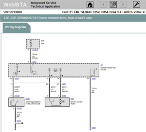
As a regular practice, you should subscribe to www.bwmtechinfo.com and use the wiring diagrams provided in webISTA. To access these diagrams you will need to enter the last seven digits of the VIN. This insures that you pull up the diagram specific to the vehicle you are working on and the correct variant. Aside from looking at a wiring diagram, you can select links on the page to take you to additional information such as the component location and the connector view. In the mid-’90s and later years, controls units would be placed in each door controlling all of the functions of those doors, including power window operation.
Starting in March of ’94 up to September of ’95, the driver’s side power window switches sent commands to all of the door modules including the driver’s side to open or close through a P-Bus. This network connects the GEM (ZKE IV), all power window switches, all door modules, sunroof module, and the driver’s side/passenger’s side seat control module with and without memory functions. The P-Bus can only be interpreted by scan tool diagnostics, but you can measure the voltage signals with an oscilloscope to verify the bus is up and communicating.
As you can tell by now, these systems have evolved through the years. Focusing on GM III, GM IV and GM V, you should know the differences among the applications. For example, GM III only uses individual door modules on the front two doors. Through the P-Bus, the door modules are wired into the GM. The GM directly receives rear door switch inputs and also controls the power window motors. In addition to power window control, a safety feature was added to prevent anything from getting pinched in the window when going up. A pinch-protection switch runs along the top of the window seal. If the door module reference voltage is grounded, this means something is pinched in the window. As a result, the window is sent down for one to two seconds. A 1.2kOhm resistor is wired between to the reference voltage and the ground to detect if there is an open circuit in the pinch-protection switch.
With a GM IV system, there are no individual door modules. The GM is receives all door switch inputs and the anti-trap signal and directly controls the front window motors. The rear windows are controlled by a relay module, which the GM controls.
On GM V systems, the GM is in total control of each of the window motors directly. It receives all of the door switch inputs. With four-door sedans, all four windows have the one-touch feature in both directions and each window has and anti-trap switch built into the upper window seal. This is not true for convertible models. There is no anti-trap switch, so there is no one-touch operation in the up direction for the passenger door. The driver’s side door still has the feature (for tolls, etc.), but window operation is limited to eight seconds by the GM V module since it is in direct control of all window motors. This is enough time to move the window all the way from fully open to fully closed. In the ’04 model year, anti-trap switches were eliminated in convertibles, and a new type of indirect trap protection was employed. The GM used the window position (through the Hall-effect sensors), direction of travel, and current draw to determine if something was jammed in the window. Of course, the windows had to be initialized for this to work, and the window cannot bind in any direction as the increase in current will stop power window operation.
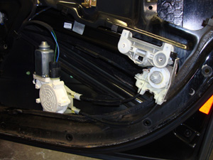
This 3-Series has cable-driven window regulators. They’re lighter and simpler to service than the scissors-type, but more sensitive to binding glass.
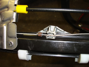
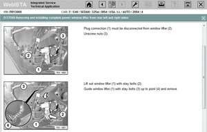
For instance, on the E46 chassis (3-Series) cable-driven window regulators move the windows up and down. They are lighter and simpler to service than bulky metal scissor-type regulators, and it is especially important that the windows are installed properly and the glass is not binding in the window tract — high current draw will make window operation inconsistent. When servicing the windows, you should only apply a small amount of light grease to the sliding mechanism. Cables do not require lubrication, so do not apply grease to them. When separating the window from the regulator, you need to always replace the glass holder bushing. Do not over-tighten this nut and bolt as you will damage the holder and possibly the glass. Once again, the specific procedure for fitting components can be viewed in the REP pages within webISTA with a paid subscription to www.bmwtechinfo.com. Since the door panel needs to come off, it is probably a good idea to order the correct door panel clips while you are ordering the window regulator and/or motor for your repair. These are the details that lead to a trouble-free repair.
Understanding computer-controlled systems and their layout allows you to come up with a diagnostic plan using your GT1/iComm/ISTA, or equivalent, and back up your findings with electrical testing. In future issues, we will review the newer E90, E60, and F01 chassis, so keep an eye out for the bimmer pub at your BMW dealer’s parts department.

0 Comments