Subaru vehicles are equipped with either a conventional suspension system or an air suspension system. Both systems utilize McPherson struts as front suspension assemblies. The advantages of Subaru’s McPherson strut-type front suspension are ease of serviceability, compactness, fewer parts, longer wheel stroke, longer service life and no camber or caster adjustments. The major parts of the L-series and XT front suspensions are the damper and coil spring, the transverse link, the leading rod and the stabilizer. The front struts on ‘85 and ‘86 model year 4WD vehicles contain adjusting nuts for increasing the front ground clearance.
Conventional Suspension Systems
Legacy vehicles use an improved design L-shaped lower control arm for increased lateral rigidity, vibration control and reduced road noise and vibration. The camber angle is adjustable on Legacy vehicles. A negative scrub radius is employed to improve braking stability and anti-dive geometry is used to minimize braking dive.
The Justy front suspension is similar to the L-series front suspension system, however, this system uses trailing rods. This system has a 15 mm positive scrub radius and only toe-in is adjustable.
Two types of rear suspensions are used on Subaru L-series and XT vehicles. The rear struts are mounted on the inner and outer arm assemblies attached to the rear crossmember. Some models are also equipped with stabilizer bars.
This system uses a dual lateral link lower arm with offset parallel links for increased stability. The rear toe-in is adjustable and it increases during corning to improve stability. A stabilizer is standard equipment, and anti-lift geometry works in conjunction with the front anti-dive geometry to minimize braking dive. Non-adjustable negative camber is also used for improved cornering stability.
The rear suspension on Justy vehicles includes an independent strut, with a coil spring mounted between the crossmember and transverse link. The transverse arm is attached to a trailing arm. The rear toe is adjustable.
Rear ground clearance on 1985-86 model year 4WD vehicles can be adjusted by changing the location of the seat in the notched plate. To do this, the shock absorber must be removed from the vehicle and compressed with coil spring compressor 926110000 until the lower seat can be freely rotated to the desired position.
Front ground clearance adjustments are made on pre-1985 model year 4WD vehicles in the same manner as ‘85 and ‘86 model year vehicles. Rear clearance adjustments on pre-1985 model year 4WD vehicles can be made by changing the mating position of the inner and outer serrations of the torsion bar. Turn the bolt located under the rear seat on hatchbacks, sedans, and station wagons. On Brats make this adjustment from under the vehicle.
Air Suspension System Overview
The Subaru air suspension system is composed of the following components: compressor, air tank, drier, air discharge solenoid, air charge solenoid, pressure switch, control unit, air springs (4), vehicle height sensors (4), and air spring solenoid valves (4). The most recent Subaru vehicle equipped with an optional air suspension system was the 1994 Legacy.
If the control unit receives a signal from the height sensors indicating the ground clearance is too low, it signals the solenoid valve at the affected spring to open, allowing compressed air from the air tank to enter the spring. When the proper ground clearance is achieved, the control unit closes the solenoid valve. Whenever the pressure in the air tank drops below a set value, the pressure switch signals the control unit to activate the compressor motor and the charge solenoid valve. Air is then forced into the tank until the pressure switch opens. If a load reduction causes the ground clearance to exceed the set value, the height sensor signals the control unit to open the affected spring’s solenoid valve and the discharge solenoid valve in order to vent the excess air.
The air springs are designed to increase riding comfort. Each spring is equipped with a variable dampening shock absorber. The metering pin in the shock absorber has a stepped diameter that varies the dampening effect of the shock absorber according to the wheel stroke. When the wheel stroke is small, the small-diameter portion of the metering pin provides clearance between the pin and the bore, lessening the dampening force. When the wheel stroke is large, the large-diameter portion of the pin fills the bore and restricts oil flow to the orifices in the piston and disc valves.
The control unit in the air suspension system maintains a set ground clearance. There are two ground clearances: NORMAL and HIGH. The HIGH setting adds 30 mm (L-series, XT) or 40 mm (Legacy) to the front ground clearance and 35 mm (L-series, XT) or 40 mm (Legacy) to the rear ground clearance. The computer responds to a change in load by adjusting the air volume in each spring. By maintaining the preset ground clearance, optimum fuel efficiency is maintained and headlight projection is held constant. Ground clearance is automatically lowered from the HIGH to NORMAL position when the vehicle speed exceeds 55 mph (L-series, XT) or 54 mph (Legacy). Ground clearance is automatically reset to the HIGH position when the vehicle speed drops to 40 mph. This also contributes to the stability and fuel economy of the vehicle. 1985 L-series vehicles automatically go to the HIGH setting when 4WD is selected.
The compressor is equipped with an electric motor and is activated by a pressure switch on the air tank. The drier is filled with silica gel, which absorbs moisture from the air in the system and prevents water from freezing in the pipes. The air discharge valve is controlled by the control unit and functions to discharge air from the system. Moisture is purged whenever air is discharged.
The air tank maintains a readily available supply of compressed air sufficient to raise the vehicle from the NORMAL position to the HIGH position. When air pressure in the tank drops to approximately 109 psi (755 kPa), a pressure switch located on the tank closes, activating the compressor motor. When pressure builds to approximately 137 psi (941 kPa), the switch opens and the compressor operation ceases. Air is released from the tank to the springs through the air charge solenoid valve.
Each air spring is equipped with a solenoid valve. Solenoid valves for the front springs are located near the strut mount. Valves servicing the rear springs are attached to the spring assembly. All solenoid valves are operated by the control unit, and they open and close to charge or discharge air from the spring.
Each air spring also contains a height sensor. The height sensor is an integral part of the spring. Consisting of a magnet and a reed switch assembly, the sensor indicates the height and load of the vehicle. Each spring is also equipped with a rubber stopper to limit the minimum shock absorber travel.
Note: The air springs and height sensors are not serviceable and must be replaced as a unit.
The control unit is located under the driver’s seat. It controls the solenoid valves based upon input from the height sensors, speed sensor, and selector switch.
The selector switch, located on the dash, may be used to select NORMAL or HIGH ground clearance. The switch will illuminate when the HIGH setting is selected, and flashes in case of trouble in the system. On some model year vehicles, the switch has been discontinued to comply with federal standards relating to passive restraint requirements.
A warning lamp on the dash indicates the ground clearance setting. It also flashes if the computer detects trouble in the system.
Note: When the lamp is flashing, the computer will not respond to inputs.
1988 Model Year L-series Operation
The switch operation is similar to previous models except that when the height control switch is pushed in once, the switch remains depressed. Previously, the switch would return to the outer position. This is the HIGH position mode. When it is pushed in a second time, the switch is released and the vehicle is returned to the NORMAL position.
When the height control switch is in the HIGH mode, the height control indicator light will blink as the vehicle rises. When the HIGH position is attained, the light will stop blinking and remain on. When the height control switch is set in the NORMAL mode, the light goes off immediately.
No blinking takes place while the vehicle returns to its normal height.
Self Diagnostics
In the User Mode, the height control indicator light blinks rapidly whenever a malfunction occurs. To determine the failure, a D-Check must be performed.
Note: Refer to the service manual, section 4-1, to review the self-diagnostic procedure.
Code Interpretation
The ECM checks ten components. Each component has an assigned position in the sequence.
Normally Functioning Components
For the Start Sequence the HIGH light comes on for 1.3 seconds, then the light goes OFF for 1.3 seconds and the cycle repeats, should no failure exist.
Malfunctioning Component
- Light on 1.3 seconds
- Light off 1.0 seconds
- CODE starts–on 0.5 seconds then off for 1.5 seconds equals Code 1
(RF height sensor)–The cycle repeats after 1.5 seconds.
Multiple codes are displayed in numerical sequence with the light off for 1.5 seconds between each CODE.
Example: Trouble Codes 1 and 3 would flash the startup sequence on 1.3 seconds, then off 1.0 seconds. Code 1 is a single 0.5 second flash (RF height sensor). The light will be off for 1.5 seconds followed by three 0.5 second flashes on followed by 1.5 seconds off for Trouble Code 3 (RR height sensor). The cycle then repeats itself.
Perform the following to return to the User Mode:
- Turn the ignition off.
- Turn the ignition back on.
- If the fault(s) is corrected, the height control indicator light will function normally.
- If the fault(s) is not corrected, the height control indicator light will flash rapidly.
Fuse Block
In order to erase the memory, turn the ignition off. Then remove fuse #5 from the fuse block or disconnect and reconnect the battery.
Note: Do not disconnect the battery or remove fuse #5 before accessing the long-term memory. This will erase any stored faults.
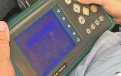
Note: Select Monitor diagnostics are available on Legacy vehicles in addition to conventional self-diagnostics. Complete details are available in Legacy Service Manual Section 4-1.
Legacy Air Suspension
The Legacy air suspension system has been enhanced to reduce the time required to raise or lower the vehicle. The air compressor is activated immediately due to the air charge solenoid remaining open for a longer period of time (25 seconds). A self-diagnostics connector is located under the dash. The trouble codes are transmitted through the height indicator switch lamp.
Air Suspension Servicing Precautions
Always observe the following precautions when servicing any component of the air suspension system:
- Using air pipe remover 926520000, vent air from the front springs before servicing.
- Activate the solenoid valve to vent the rear air spring before servicing.
- O-rings are used to seal air-line connections. Apply the specified grease to the O-rings before reassembly.
Suspension Servicing Precautions
- Torque the bolts to specifications.
- Cap the brake hose ends.
- Protect the brake backing plate and drum.
- Bleed the brakes after reassembly.
The above general suspension servicing precautions are applicable to servicing the air suspension system as well.
Wheel Alignment
Legacy, Impreza and Forester Camber Adjustment
Camber is adjusted by rotating the eccentric adjusting bolt located at the base of the strut (upper bolt).
Camber and caster are not adjustable on Subaru L-series, XT or Justy
vehicles. Toe is the only adjustment that can be made. Before measuring toe, inflate all tires to the specified pressure, unload the vehicle, and park the vehicle on a level surface. Then, measure the toe with a toe gauge. See the appropriate model year service manual for specifications.
If toe is not within the specified range, set and lock the steering wheel in a straight-ahead position. Then, loosen the lock nuts on the left and right tie rod ends, and turn the tie rods equal amounts until the toe is within the specified range. Then, tighten the lock nuts to the specified torque. The rear toe adjustment on Justy vehicles is made by rotating the trailing link mounting bolt. Scales, or increment marks, on the mounting bolt correspond to approximately 0.12 in (3 mm) in toe variation.
The rear toe-in angle on the front wheel drive Legacy model is adjusted with a two-piece bolt/adjusting wheel located in the lateral link. For every incremental change made on the adjustment bolt, the adjusting wheel must be rotated in the opposite direction by the same increment.
The rear toe on all wheel drive Legacy, Impreza or Forester models is adjusted by a one-piece cam bolt which is located in the lateral link.
Axles Components and Construction
Front Drive Axle
The front drive axles on Subaru vehicles are coupled to the transmission by double offset joints (DOJs) and to the hub and disc assembly by constant velocity joints (CVJs). The CVJs permit smooth power transfer to the wheels regardless of the steering angle.
The XT6, Legacy, Impreza and Forester configuration has been carefully designed to reduce the unsprung weight of the vehicle for better tractability. The hub is pressed in the axle bearing. This eliminates weight transfer to the CVJ, which improves the axle shaft serviceability and eliminates the need for an axle shaft puller or installer.
The front axle shaft diameter has been increased in order to handle the higher torque of the H-6 and later H-4 engines. The CVJ splines have also been lengthened to accommodate the new hub design. The castle nut used on the L-series XT has been replaced with a standard type axle nut and adjusting cap on the XT6. This allows for a more precise adjustment. 1990 model year and later Legacy vehicles use axle shafts similar to the XT6,
however a caulking nut is used in place of the axle nut and adjusting cap. This adjustment system is also used on Impreza and Forester models.
Service Precaution: If the front axle nut is loosened or tightened when the tire is touching the ground, the tapered axle bearing may be damaged.
The rear axle on front wheel drive L-series and XT vehicles consists of a spindle welded to the rear trailing arm. On Justy vehicles, the spindle housing is bolted to the transverse link and the trailing arm. The hub is attached to the spindle by tapered roller bearings on L-series and XT vehicles. Legacy, Impreza and Forester vehicles use a non-serviceable ball bearing and hub unit. The rear axles on pre-’87 4WD vehicles are connected to the differential and to the housing by DOJs. On ‘87 model year and later vehicles, the outer joint is a CVJ. The axle spindle is supported by bearings inside the housing, and the housing is welded to the rear trailing arm.
The serrated drum or hub and disc assembly is held to the spindle by a castle nut and cotter pin.
The Legacy, Impreza and Forester use a caulking nut in place of the castle nut and cotter pin. On these models as well as XT6 vehicles, the hubs are pressed into the axle bearing which eliminates weight transfer to the CVJ. Axle shaft serviceability is also improved which eliminates the need for an axle shaft puller or installer. The XT6 uses an axle nut and adjuster cap to secure the axle shaft to the hub, while the others use a caulking nut.
Axle Servicing Precautions
- Correctly identify the replacement axle shaft. Several types are available.
- Use special tool 921122000 and adapter plate 922493000 when removing the front drive axle.
- Use special tool 925130000 for L-series vehicles when replacing the front drive axle.
- Use only Molylex No. 2 grease p/n 723223010.
- The inner-rear DOJ is smaller than the outer rear DOJ. Do not reverse the positions during installation.
- Be sure to remove the large clip from the neck of the DOJ outer race before trying to remove the outer race from the shaft.
- Install the DOJ cage with the cut out portion toward the shaft end.
- Always use new cotter pins, lock tabs, or stake nuts and spring pins.
Eliminating Front End Vibration
Determining the source of front-end vibration occurring at cruising speed can be difficult. The trouble may lie in the suspension system or the steering system, or the cause may be tire and wheel imbalance. Discovering the vibration source is often a process of elimination. Begin by checking potential problem areas such as steering gear backlash, tie-rod ends, wheel bearings, ball joints, tire mounting lugs, leading rod bushings, etc. If the search does not turn up any problems, check the tires and wheels for imbalance. Be sure the wheel balancing equipment is properly calibrated by rotating a balanced wheel 180 degrees on the balancer shaft and rechecking the balance. The balance should remain unchanged if the balancer is properly set.
Note: The red dot on the tire (radial force variation) and the gray dot on the wheel must be aligned when the wheel is balanced.
Notes and Cautions
Air Suspension System
The air spring and height sensor are not serviceable and must be replaced as a unit.
When the HEIGHT lamp is flashing, the system computer will not respond to inputs.
Use the special tool (air pipe remover) to vent air from the front springs.
Before servicing the rear spring, activate the solenoid valve to vent air from the spring.
Use the proper O-rings to seal air line connections. Apply the specified grease to the O-rings before assembly.
General Suspension Servicing Precautions
Tighten all bolts to the specified torque.
Insert the air bleeder cap into the disconnected brake hose prevent damage to the backing plate and drum.
Always bleed the brakes after reassembly if the brake lines have been disconnected.
Axle Servicing Precautions
Correctly identify the replacement axle shaft. Several types are available.
Use the appropriate special tools when removing or installing the front drive axle.
On ‘85 and ‘86 model year rear drive axles, the inner DOJ is smaller than the outer DOJ. Do not reverse their positions.
When disassembling the DOJ, remove the large clip before removing the DOJ outer race.
Install the DOJ cage with the cut out portion toward the shaft end.
Always use new cotter pins, lock tabs, or stake nuts and spring pins.
Wheel Balancing
The red dot on the tire (radial force variation) and the gray dot on the wheel must be aligned when the wheel is balanced.
Download PDF


0 Comments