
How two M-B systems work in overall view
K-Jetronic Fuel Injection

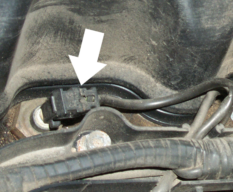
Injector and bracket
Mercedes-Benz cars have a long history with various gasoline injection systems, including exotic versions as the Diesel-like direct injection used in the Gullwing SL of the early 1950’s, spraying fuel right into the combustion chambers themselves. The M-B fuel injection system you’re most likely to find in your workbay today, however, is one generation or another of the Bosch K-Jet series, beginning on some cars in the 1970’s and continuing well into the 1990’s. Shortly after emissions regulations began to require engine management systems that adjust air/fuel mixtures in response to a feedback signal from the exhaust system’s oxygen sensor, the fuel injection system underwent a major evolution into the KE-Jet. K stands for the German word for continuous; E stands for the German word for electronic. We won’t cover every detail of every variation of the K- and KE-Jet systems. The purpose here is to explain how the systems work in overall view. If you understand the overall system, you can diagnose and repair it if it fails.
The hallmark of the K-Jet systems, alone among fuel injection systems in widespread distribution, is this: As long as the engine runs, they spray fuel through their nozzles continuously. The injectors are entirely mechanical, opening at about 3.8 bar fuel pressure (gradually declining to 3.0 bar with use) and delivering whatever volume the system sends them, mechanically corresponding to the volume of intake air. There are no electrical parts or connections to these injectors; nothing turns them on or off; nothing pulses or cycles them in any way except the hydraulic force of the gasoline. High speed photography sometimes shows the nozzles ‘chattering’ at a frequency of about 1500 Hz, but that is entirely a consequence of the resonances of the needle, of the spring and of the viscosity and delivery speed of the fuel. Certain K-Jet injectors were microscopically formed so the needle ‘walks’ around the opening, further atomizing and vaporizing the fuel. To insulate the injectors from the engine’s heat and vibration, they don’t thread into the manifold but are just pressed in by hand, held by nonconductive rubber collars. The hex head only serves to steady the injector while you connect or disconnect the fuel line. Many injectors include an air shroud around the tip. Particularly at idle speeds, this air shroud insulates the fuel spray cone from the sides of the manifold where it might condense. The focused, high-speed airstream also helps vaporize the fuel even when the engine is turning slowly with no load.
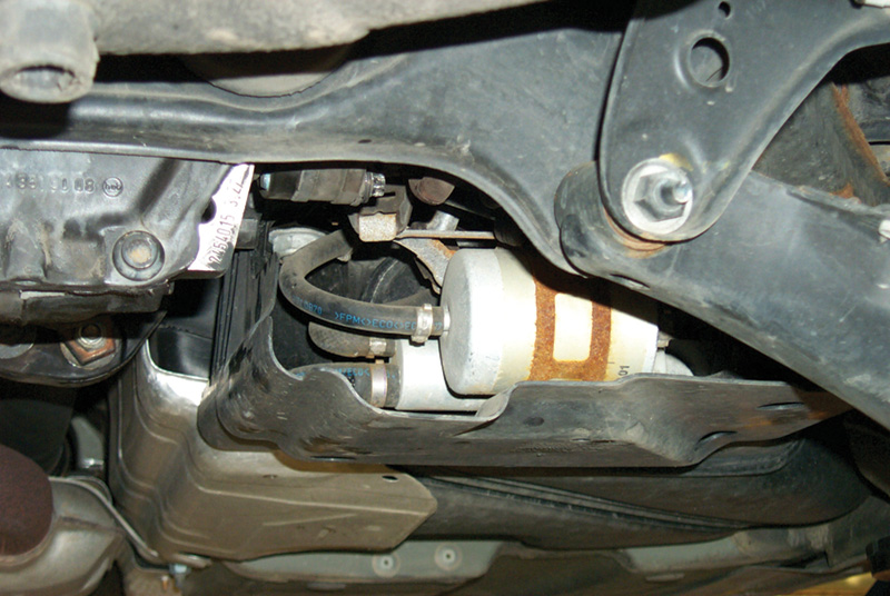
Pump and filter
But let’s start where the fuel starts, at the fuel pump. For the earliest and simplest form of the K-Jet, this was the only electrical component, toggled on and off by the fuel pump relay on the firewall. There were no sensors, no computer, no actuators. Some of the technical literature at the time referred to the “airflow sensor,†but as we’ll see, the word sensor meant something entirely different from the way we ordinarily use it now. In principle, the fuel pump could have been mechanical, driven by a crankshaft pulley. But you want the pump away from the heat and near or inside the fuel tank to minimize vapor lock, while the engine and accessory drive is at the other end of the car.
The basic K-Jet fuel pump has become the de facto automotive standard for all fuel injection systems. It’s a small but powerful electric motor with a positive displacement hydraulic pump on one end of the shaft. Fuel fills and runs through the pump as it runs, cooling the armature windings. While the carbon brushes and copper commutator are surrounded with gasoline (recall that fuel bathes everything inside the motor), there is no room for air or oxygen, and thus nothing can catch fire. Sparking from an electric motor’s carbon brushes could ignite fuel vapor in air, but sparking submerged in liquid gasoline can’t.
Early versions had two speeds: on or off. All the fuel not injected into the intake runners recycled back to the tank, keeping the underhood fuel plumbing relatively cool. Some later versions included such complications as an additional, lower-current pump delivery rate for quiet low-speed driving, vehicle-speed limits by electronic control of the ground circuit, multiple pumps in series (one for pressure, the other for volume) and so on.
The first pumps worked by ‘roller cells,’ cylindrical bearing rollers held captive in channels around the outside of a drivewheel slightly eccentric with respect to the housing. As the rollers moved toward and away from the center as the drivewheel rotated, they drew the fuel from the tank and drove it toward the engine by displacement. ‘Gerotor’ pumps, internal/external gearsets that work like engine or transmission oil pumps, replaced them. Additional designs include cycling-vane and peripheral-pump designs and, on current M-B’s, counterrotating helical spindles, forcing the fuel through with a geometry just like a scroll-supercharger’s. In each case, the object is to move the fuel and build the pressure quickly and reliably. Changes in pump design have frequently been to make the pumps quieter. Because the fuel cools them so effectively, fuel pump electric motors can be surprisingly small for their power. You’ll find most K-Jet pumps draw between 6 and 10 amps. A lower current should flag resistance in the circuit; a higher current means an internal short or a fluid block slowing the pump and making it work harder. A representative good pump for a six-cylinder engine delivers a liter in 40 seconds. Larger displacement engines get more fuel.
The pump for any given model can deliver more fuel than the engine could burn under the most adverse fuel-demand conditions: wide-open throttle at 40-below. This excess pump capacity guarantees full engine function and full fuel pressure even under extreme conditions. About the only factors that can prevent a mechanically and electrically functional K-Jet pump from delivering enough fuel to the engine are a completely plugged fuel filter (very rare) or a crimped or blocked fuel line. These problems ordinarily cause a noisy pump since it has to work harder while they’re present, and you’ll hear the pressure pulses. If rust formed in the system after the fuel filter (because of moisture in the gas, perhaps), there can also be clogs at the small filters internal to the fuel distributor and to the injectors themselves.
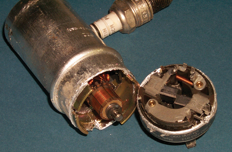
Commutator and brushes
In the fuel outlet of each pump there is a fluid check valve. Its function is to retain fuel in the injection lines to prevent vapor lock and to keep the plumbing full of pressurized liquid fuel for the next engine-start. The check valve merely seals the fuel in the system; the pressure derives from the pressure accumulator (see below). Long cranking times are the first symptom of a failure in the check valve or the pressure accumulator. For diagnostic purposes, a ‘long cranking time’ is more than four seconds before the engine fires.
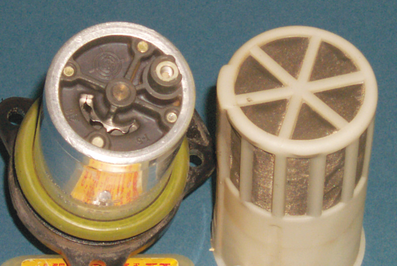
Pump and screen
The fuel goes directly from the pump to the fuel filter. While this is the standard layout now, it is worth recalling that when carburetors walked the earth, fuel filters were often between the tank and the pump. Such an arrangement would often mean vapor lock with modern fuels in a fuel-injected vehicle (it often meant vapor lock with older fuels in carbureted vehicles, too!). Putting the fuel pump ahead of the filter, however, means the cleanliness of the fuel from the filling station is more important than ever. Any particles of grit or rust go through the fuel pump largely unfiltered, except for the coarse-mesh screen just ahead of the pump inlet. That screen serves mostly to block particles large enough to jam the pump.
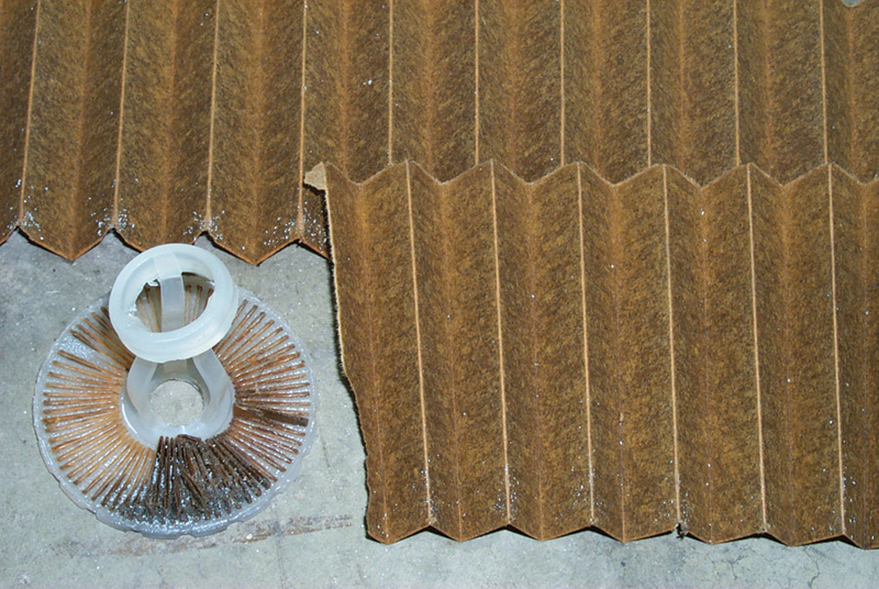
Accordian paper
Once it was standard practice to replace a fuel filter with every ‘tune-up.’ But there haven’t been ‘tune-ups’ since the demise of ignition contact points, back in the 1970’s. Modern fuel filters contain a large area of super-fine-mesh, accordion-fold filter paper capable of removing particles down to single-digit-micron sizes and of absorbing or neutralizing most gums and tars.
A filter actually cleans more effectively after it has been in use for some time and has collected a patina of dirt on the active filter surface. Unless there is clear, demonstrated need to replace a fuel filter – that is, a failure of a good fuel pump to deliver the volume and pressure specified by the carmaker for that model – it is a mistake to replace the one on the car.
After the fuel pump and filter on the hydraulic circuit comes the accumulator (these three elements are often lined together in a row on early systems). The accumulator consists of a container with a diaphragm separating the fuel and the air chambers and a spring to hold pressure from the air side of the diaphragm. The functional analogy to accumulators in automatic transmissions is close, but not exact. In an automatic transmission, an accumulator absorbs and stores the hydraulic application pressure to soften and extend clutch or band engagement time. On a K-Jet, the fuel pressure accumulator absorbs and stores the fuel pressure, but to smooth out the pressure peaks resulting from pressure pulses from the pump (reducing noise and smoothing fuel flow) and to retain pressure in the system when the pump turns off. If you measure the system pressure after the engine shuts off, you should find at least 2.7 bar after 10 minutes and 2.6 after twenty. Not all K-Jet systems require fuel pressure accumulators because in some vehicles there is enough volume in the lines and components.
As mentioned earlier, K-Jet injectors release fuel anytime the pressure is greater than about 3.8 bar (varies somewhat by model and year). But that leaves sufficient residual pressure in the system to keep it primed for a quick restart and to prevent vapor lock in almost any ambient or underhood temperature.
If you find a K-Jet system that does not hold pressure after shutdown, especially if it makes audible ‘electric-motor’ noise corresponding to pump speed, check the pressure accumulator for a broken spring or ruptured diaphragm. A direct pressure check is the test procedure, and you can measure that most conveniently at the fuel distributor inlet. Inspect the pump’s check valve as well by confirming that the system holds pressure after engine shutdown. If those components are good, look for a dribbling injector.
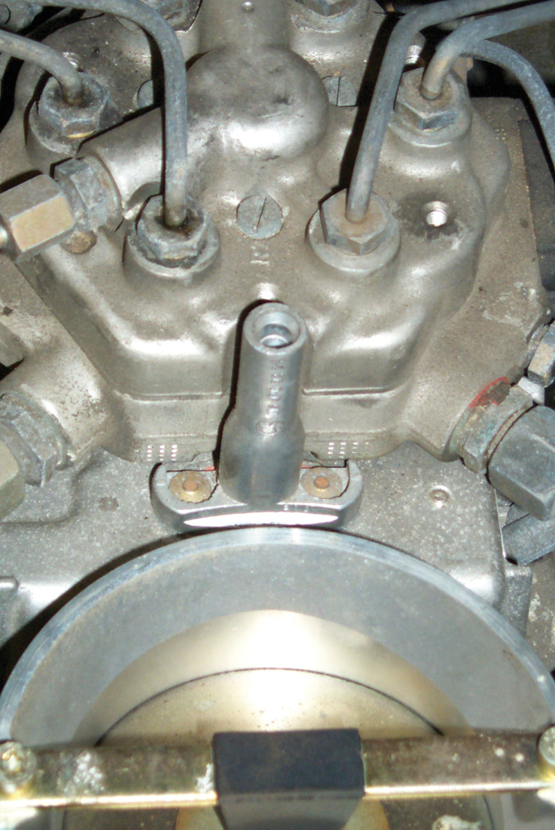
As the gasoline continues through the line, it encounters one of the most interesting devices in automotive technical history, the K-Jet fuel distributor. The name suggests that, like an ignition distributor sorting high-voltage spark to the appropriate plug in firing order, the fuel distributor sorts metered quantities of fuel to the corresponding cylinders. But it doesn’t work this way: Instead, all the cylinders get fuel all the time. The distribution in question is sorting the same quantity of fuel to each cylinder simultaneously. A K-Jet bank of injectors can hold the cylinder-to-cylinder mixture variation to six percent or lower. Carburetors typically varied by 40 to 60 percent (see “What Happened to Carburetors?†below).
KE-Jet
The fuel distributor has a separate delivery tube for each cylinder’s injector. Inside the distributor, each fuel line ends in a differential-pressure regulator metering fuel into its line, based on the fuel pressure and on the amount of deflection of the spring-steel diaphragm below it. While all the pressure regulators share the same hydraulic force in the conjoined lower chambers, they have separate chambers above, each filled through its own laser-cut metering slot. They deliver a precisely equal quantity of fuel to each cylinder because of the precisely equal machining of the components (the control plunger and its sleeve, a matched set, are machined to an accuracy of 0.00025-in).
This level of precision depends critically on the assembly conditions and controls at the factory, so you are most unlikely to succeed in reassembling a fuel distributor on a workbench and have it work properly – or even just not leak. It’s interesting to pop a defective one open just to see what’s inside, but don’t count on using that one again! If you find one plugged internally, get a replacement and return that one for remanufacture. You can remove the inlet filter (if present) or the control plunger and the filter surrounding it and the metering slots for cleaning, but these are not standard maintenance procedures. If you do find particles in those filters, replace the main filter because it’s leaking grit through.
Each of the fuel injection lines ends in the center of a small, fuel-filled chamber with a steel diaphragm on the bottom. Below that diaphragm is another chamber of the same dimensions but without an injection line. When there is higher pressure above the diaphragm than below, the force bends the diaphragm slightly down and drives fuel through the fuel line and (assuming it exceeds the opening-pressure threshold) out the fuel injector tip. When the pressure difference between the two matching chambers is lower, the diaphragm moves back up and reduces the amount of fuel injected. If the pressure in the lower chambers is greater, the steel diaphragm rises and shuts off fuel flow entirely. The pressure of the fuel and the vacuum in the intake manifold also affect the fuel volume. Keep in mind, it is the pressure differential between the chambers that determines the diaphragm position, not the pressure itself. But for a given diaphragm position or injection-line opening, the upper chamber pressure (with the intake manifold vacuum) determines the momentary volume of fuel flow.
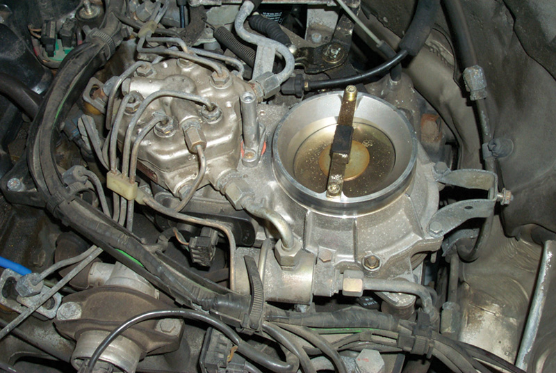
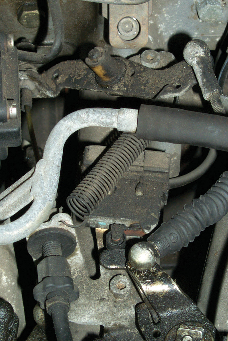
Airflow plate
The K-Jet airflow sensor is unlike any intake-air measurement device on any other system, even the swinging-door sensor on Bosch L-Jet systems, which it vaguely resembles. The fuel distributor and the airflow sensor are one assembly, described jointly as the mixture-control unit. The K-Jet airflow sensor physically, mechanically determines the fuel flow by changing the pressure in the upper chambers of the fuel distributor.
The airflow side of that unit consists of a finely machined air cone with an air flap in the center. This air flap occupies a position in the intake airflow between the air filter and the throttle plate, and the flap moves in response to air moving past it, drawn into the engine when the throttle opens. Movement of the air plate corresponds to the volume of air passing it because of the very precise tapering of the air funnel. The open cross-sectional area around the cone reflects the volume of air, and the mixture control unit thus insures there will be a larger quantity of fuel metered for a correspondingly larger amount of air and vice-versa. As the air plate and lever move from the rest position, the lever moves the control plunger to uncover more of the fuel control slots, increase the pressure in the fuel distributor and the amount of fuel delivered.
Air inlet
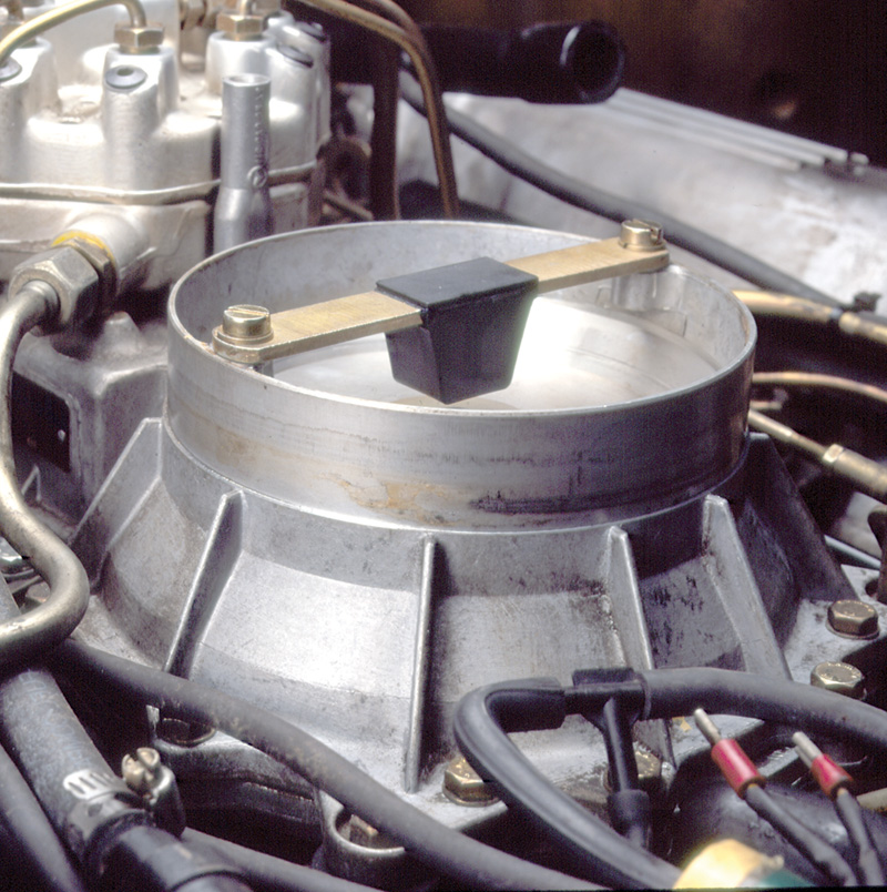
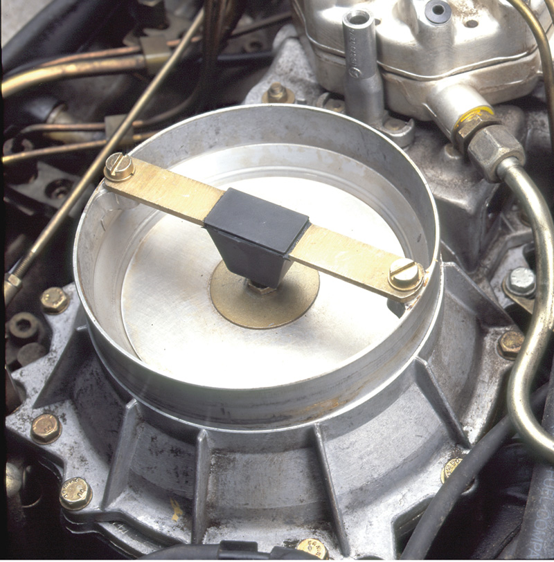
There is seldom any reason to loosen or remove the K-Jet airflow plate from its lever because its precise centering is so critical (if it touches, it can snag and stick in the funnel bore). If you need access to any part of the airflow sensor below the plate, you have to remove the sensor from the intake tract anyway. Unless you have a special tool for the purpose, a good way to re-center the plate if you have removed it is to fit paper around the perimeter while you tighten the positioning bolt. If you use paper of the uniform, correct thickness, you’ll then have a uniform, correct gap all around the sensor plate. Absent that perfect paper, use toilet paper: It will be too thin alone, but you can build up enough for the right gap with further wraparounds.
Mercedes-Benz K-Jet airflow plates usually have curved or shaped top surfaces, not a feature of all Bosch K-Jet systems. The effect of the curved surface is to aerodynamically allow through greater airflow compared to a flat sensor plate of the same diameter. Each airflow sensor plate also has a stop bar above it, combined with a rubber bump-stop. The purpose of those elements is to allow the lever and plate to bounce above the center of the funnel and spill backpressure should there be a backfire through the intake manifold. With these elements, the airflow plate and lever can survive a backfire, usually without damage. The funnel is tapered above, partly to orient the incoming air around the plate and partly to provide pressure relief should there be a backfire.
While Bosch K-Jet systems on many cars draw the intake air up through the airflow sensor and through a tube to the throttle body, on most Mercedes-Benz vehicles the air flows down through the air funnel and into the engine. Among other advantages, this eliminates ‘false air’ coming through a cracked, porous or loose air hose. Functionally, the system works the same way with just a change in the geometry of the air sensor lever and fulcrum. While the air flap does present an obstruction to the intake airflow, its aerodynamic resistance is quite low, so there is no vacuum to speak of generated between it and the throttle plate. All of the intake, except for what comes through the PCV and EGR, passes the airflow sensor. Idle air, in particular, transits the sensor.
At engine-shutoff rest, with no air passing through the sensor, the spring tension and weight on the arm bring the lever to a position in which it moves the control plunger of the fuel distributor to shut off all fuel flow. While early and late fuel distributors have different internal plumbing, most of them have fuel system pressure above the control plunger, and the return force of the airflow arm must be enough to overcome this as well. Depending on the application, this return force comes either from a spring or from a counterweight on the opposite end of the lever.
As emissions requirements tightened, there was a late version of the K-Jet system, sometimes called the K-Lambda, that used an oxygen sensor for mixture feedback information and a separate frequency valve on the fuel return circuit. By duty-cycling the return flow, the system could fine-tune intake mixture by fine-tuning the fuel pressure in the fuel distributor. But to achieve the combustion control required for the next set of emissions standards, the system had to evolve into the KE-Jet.
KE-Jetronic Fuel Injection and the EHA
What distinguish the basic K-Jet injection system from the KE-Jet are the electrohydraulic actuator (EHA) and the subsystems and components involved in making it work. Because of a pressure regulator in the fuel distributor, the pressure difference between the upper and lower chambers stays about 0.4 bar, the same as the earlier K-jet. As the airflow lever moves, the control plunger routes fuel into the fuel distributor. What the EHA does is to modify the lower chamber pressure in response to the oxygen sensor feedback signal, independently of the rest of the fuel distributor. Modifying the lower chamber pressure changes the pressure differential between the chambers, changes the position of the spring-steel diaphragm and thus changes the volume of fuel delivered for the amount of air passing the airflow sensor.
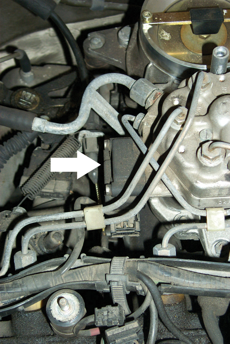
EHA
The EHA contains a variable electromagnet moving a metering plate that covers or uncovers a fuel inlet to the lower chambers. This electromagnet, like all others, is a current-responsive element. It does not work in direct response to voltage, but to amps – or in this case milliamps. The windings on most KE-Jet EHA’s should read about 19.5 ohms at room temperature.
The KE-Jet system does use a control unit to control intake mixtures and keep the combustion as close to stoichiometry as possible (as did the last versions of the K-Jet). The feedback information to constantly readjust this mixture comes from the oxygen sensor just as on most other vehicles. What is different on the KE-Jet is the way the mixture command works. In effect, what it’s doing is to control in part the flow of fuel to the lower chambers, thus controlling the pressure differential.
The EHA is a kind of electrical solenoid, but instead of moving an element suddenly and dramatically to one extreme of its travel or the other the way a starter solenoid does, the EHA merely applies a measured electromagnetic force to the metering plate, slightly bending it in one direction or the other. By varying not only the current but also the polarity of the command, the computer can change the mixture from full rich to fuel shutoff (under extended deceleration, for example). The important thing to keep in mind is that electromagnetism here, as in all solenoids, functions by current, by amperage alone. The voltage does not matter at all, except that polarity cycles back and forth under closed-loop driving; and if polarity changes, voltage does, too.
Check an EHA for continuity as described above and then for dynamic function. When the engine first starts cold, there will be a steady current of several milliamps to richen the mixture for the cold engine. Once the system is running in closed loop (two minutes after startup, at the longest), you should see the current cycling, reflecting the signal from the oxygen sensor cycling. Many testers display this as an on-off signal, but it’s actually current in milliamps reversing polarity.
If the EHA current cycles, but not within the milliamp-or-two range, check first for air leaks. If they are eliminated, you can open the ‘tamper-proof’ cap and have access to the mixture adjustment screw. This should not be a regular service – if the engine has not been apart or the fuel distributor replaced, keep looking for a vacuum leak first. If you use a sensitive amp-clamp to check the EHA at work, be sure to separate the two wires. It doesn’t matter which you measure, but if you catch them both in the clamp, the currents in opposite directions will cancel out your measurement.
The KE-Jet ECU employs several parameters when calculating the EHA control current. These include:
- Cranking signal – an electrical signal parallel to the starter solenoid current,
- Engine temperature – a reference signal dropped to a voltage corresponding to the engine coolant’s temperature,
- Intake air temperature – from a sensor in the air intake duct,
- Engine speed (TD or crankshaft position signal) – from an inductive signal generator at the flywheel,
- Engine load – from a MAP (manifold absolute pressure) sensor,
- Airflow sensor position signal and movement – from a sensor at the end of the airflow sensor lever pivot,
- Oxygen sensor or Lambda signal – from a conventional heated oxygen sensor in the exhaust stream.
For warmup, the computer sends a command current that moves the EHA valve plate to somewhat restrict fuel flow. That allows pressure to drop in the lower chambers, and the pressure differential bends the metal diaphragm down, allowing relatively more fuel to flow. When the engine reaches normal operating temperature and runs in closed loop, the ECU sends commands of varying polarity and current, causing the valve plate to cycle back and forth across its travel, thus richening or leaning the intake mixture as the need reflected in the oxygen sensor signal requires. A scope, set to monitor the EHA current and the oxygen sensor signal simultaneously, graphically indicates this interdependence.
When the computer’s sensors indicate deceleration (closed throttle, high engine rpm, strong intake manifold vacuum or low MAP), the ECU sends current in a polarity to pull the metering valve plate all the way back, allowing pressure to equalize between each of the chambers. The additional pressure of the small spring in the lower chamber is then enough to stop fuel flow.
The system has an inherent and transparent ‘limp-home’ mode. If one or more circuit failures mean the computer can’t send a signal to the EHA, spring tension on the valve plate brings it to a center position; and the engine continues to run just as if it had ordinary K-Jet instead of feedback-modulated KE-Jet. On most models this circumstance trips the CEL and, if the car has self-diagnostics, sets a code for whatever circuit has failed. Because the KE-Jet uses an electrically triggered cold-start injector spraying into the intake manifold log, the engine can ordinarily still start when cold.
The computer control system on KE-Jet is almost entirely for the fuel mixture; its purpose is to calculate and send the current command current to the EHA. While it has an input signal from the crankshaft position sensor and in some models from the speedometer, while on some models it includes a transmission upshift delay function (to speed engine warmup), this is not yet a complete engine management system, coordinating fuel, spark, A/C compressor engagement, cruise control and other functions into one (that comes with the next system, Motronic). Control of the ignition system rests with the EZL/AKR control unit, with only minor interconnections with the fuel system. KE-Jet is a fuel injection system only. Nonetheless, do not connect or disconnect the control unit with the ignition key on. That can yield damaging voltage spikes.
Rich and Lean Mixtures
You need more fuel during cranking and the first second or two running. Fuel enrichment continues for as long as two minutes, depending on coolant temperature. It also occurs during acceleration to accommodate the fact that air accelerates into the intake manifold more quickly than fuel. Finally, at high speeds and high loads, at or near WOT, the mixture also goes rich. In that latter mode, there is no mixture feedback function and no EHA control current; the engine runs in open loop.
CTS for fuel and ignition
The mixture goes lean not only during deceleration fuel shutoff (a throttle-closed microswitch provides the enabling signal) but, on many models, to prevent over-revving the engine into redline territory. It’s also the first tactic in the vehicle maximum speed limit, followed by shutoff of the fuel pump. Since the vehicle maximum speed is a voluntary limit agreed among Mercedes-Benz and several other German carmakers for vehicles intended for the unlimited-speed German autobahns, the limit is as high as 250 km/h, about 155 mph. On American roads, this should rarely inconvenience a driver. Deceleration fuel shutoff is disabled whenever the car is under cruise control.
You can find any one of three different coolant temperature sensors on Mercedes-Benz cars with KE-Jet: an internally grounded one-pin version connecting only to the KE control unit, a similar two-pin unit with pins for the KE and ignition control units (or one for KE and one for the fuel pump relay) or a four-pin version with two pins for KE and two for the ignition system. All use NTC resistors; that is, the resistance goes down as the temperature goes up. The four-pin versions are idiot-proof, in the sense you can plug them in any clock position and they work the same. Each second pin on the four-pin versions avoids any problem of excess resistance on the ground-return circuit. For each type of sensor, though, check the continuity of the harness back to the computer as well as the variable resistance through the sensor.
Throttle switch
There is no throttle position sensor, but there is a throttle switch with two outputs, corresponding to idle position, WOT position or (in the absence of either) any position in between. Because of the way the KE-Jet airflow sensor and fuel distributor work, there is no need for a fine-discrimination throttle-position potentiometer. Test these switches, simple on-off devices, for continuity in one position and open circuit in the other.
As important as K-Jet and KE-Jet are in the development of Mercedes-Benz fuel injection systems (and for other carmakers, actually), it’s critical to understand how the original systems worked to understand the later variations, what the changes were for, what they meant. What a good thing that every new technology has to start with the simplest version!
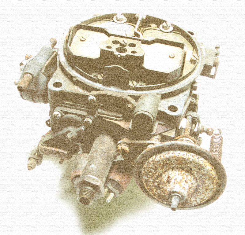
Why did carburetors go away? They were essential parts of cars practically as long as tires, and (like every thing else) they’d become more complex even as the demands of fuel economy, power and emissions friendliness in-
creased. Even on the most complicated carburetors, the vacuum and evaporation technology involved were well understood, and most vehicles could run well enough with them, even if overhaul and readjustment procedures became gradually more difficult.
The carburetor’s insoluble problems were with mixture control and fuel distribution. The proper fuel/air ratio for an engine varies considerably over load, speed and temperature. It varies also with the ‘recent history’ of the throttle, too, so you need a richer mixture at a given throttle position if the driver is in the process of rapidly opening it, and you need a much leaner mixture at the corresponding throttle positions as the throttle rapidly closes. Most carburetors used an acceleration pump or its equivalent to briefly richen the intake mixture as the driver moved the pedal toward the floor. The enrichment provided by the accelerator pump, however, was imprecise and changed over time with wear of the pump.
Carburetors could vary mixture in response to oxygen sensor feedback signals, but at the cost of increased complexity and vulnerability to dirt or contaminants. Carmakers used duty-cycled solenoids to modulate either the fuel in the main circuits or the air in the emulsion tubes. A feedback carburetor, however, could not make mixture changes rapidly enough to follow rapid openings or closings of the throttle with the precision required. What’s more, since the carburetor sits on ‘top’ of the intake manifold, there is no way to prevent the fuel just atomized and vaporized from condensing back into liquid on the manifold walls when pressure and temperature conditions favored that. Even the most sophisticated mixture-adjusting carburetor could hold total mixture within the desired range only at steady speeds, not under the quick changes of driving in ordinary traffic.
But even if the mixture problem were perfectly solved for carburetors, there is still the fuel distribution problem. This is most dramatic on inline engines with single carburetors and ‘log’ manifolds: Imagine a six-cylinder engine with a single-barrel carburetor at the midpoint of an intake manifold running parallel with the camshaft. Because the heavier droplets of fuel resist turning when the airflow does, most blow to the extreme ends of the manifold. The smallest droplets and the properly vaporized fuel make the turns easiest. In every such engine, then, cylinders one and six will get the richest mixtures and cylinders three and four will get the leanest.
This is more than a slight or theoretic problem, actually. According to Bosch experiments, a typical carbureted four-cylinder engine will have mixture variations of about 60 percent. Clearly, you have to send the cylinders getting the leanest mixture enough fuel to fire dependably; thus the richest cylinders must always run overrich. This condition means increased wear in those rich cylinders because of cylinder wall washdown from the excess fuel. It is typical in inline engines to find the first and last cylinders have the most wear (though there are other factors, like variations in coolant temperature as you get closer to or farther from the water pump).
The richer mixture naturally enough means more hydrocarbons in the exhaust, too. Multipoint fuel injection systems like the K-Jets reduce both mixture and distribution problems by a factor of about 90 percent.
|
Â


0 Comments