
There was a time when superchargers and turbochargers were pretty much limited to race cars and certain high performance applications. Now, with the newer technology and the global drive for fuel efficiency and more power, turbochargers seem to be found on almost every model. If you want a general overview of Mercedes-Benz turbochargers, their history and latest developments, see the article “More and More Turbochargers” (bit.ly/moreturbos) in the September 2016 issue of StarTuned (bit.ly/mbst201609).
Today, we will spend our time looking specifically at the turbo units found on the GLC300, and similar models equipped with the M274 engine and turbocharger package.
One thing to note when searching through the Mercedes-Benz Workshop Information System (WIS) or XENTRY Diagnosis for repair information, is that you may come across the term “Abgasturbolader,” which is the German word for “exhaust gas turbocharger.” In some cases, you may also see the abbreviation “ATL,” which also refers to that German word.
Function and Layout
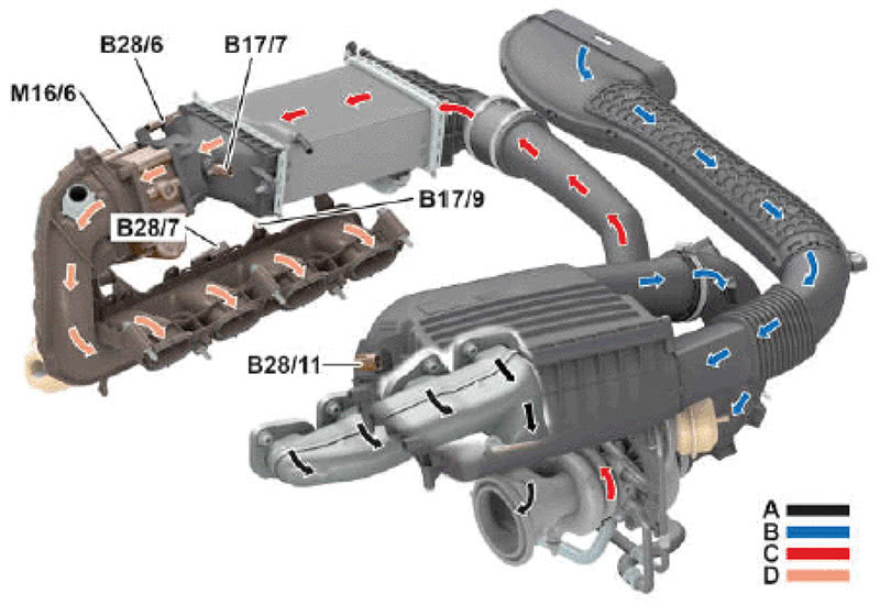
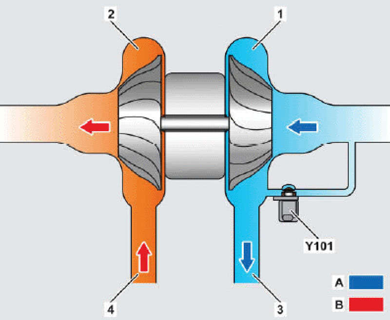
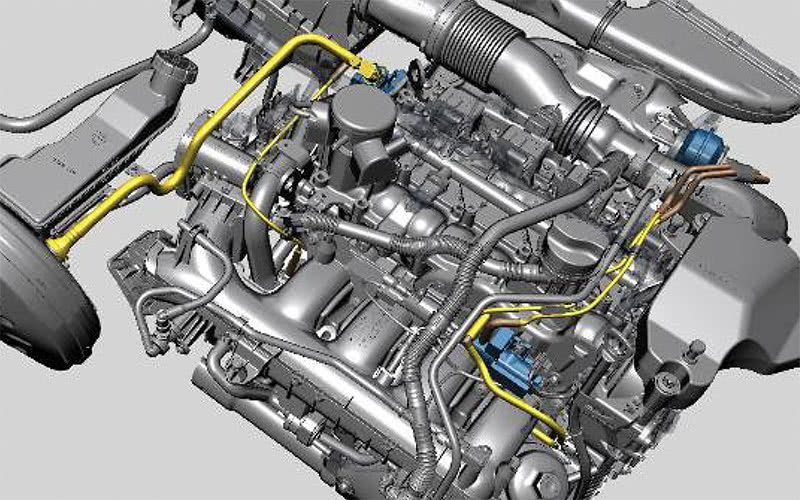
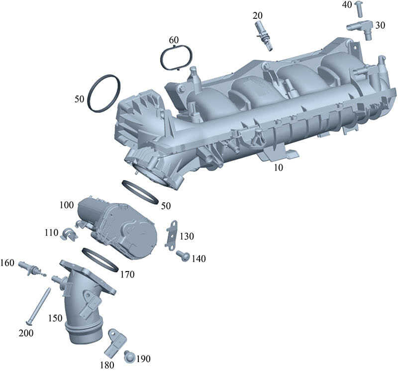
The flow and function are no different than most turbos with a charge air cooler. The ATL draws in fresh air via the air filter and the compressor inlet, and directs this from the compressor outlet to the charge air pipe. This is accomplished using the flow energy of the exhaust gases to spin the turbine wheel at a very high rate of speed. The high rpm of the compressor impeller and the increased flow rate compresses the air in the charge air pipe, causing it to heat up. Finally, the compressed charge passes through the charge air cooler, which cools the intake air wand directs it to the charge air distributor (manifold).
Understanding the Sequence for Forced Induction
This sequence is important to understand, as most of the codes and associated drivability complaints will be related to the monitoring of the sequence, e.g. over boost, under boost, and air temperature plausibility. The sequence can be broken down into three areas: boost pressure control, bypass air, and charge air cooling.
First, let’s look at boost pressure control. The ME-SFI control unit receives data from the following:
- Two charge air temperature sensors, both upstream and downstream of the throttle valve. (Remember science class? The air density is inversely proportional to temperature. Thus, the ATS signal allows for a much more accurate measurement of the air mass. Using two sensors allows the control module to monitor the ambient temperature and the engine bay temperatures.)
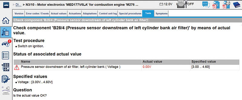
- Pressure sensor downstream of the air filter
- Two pressure sensor, both upstream and downstream of the throttle valve
- Accelerator pedal sensor (driver’s commands)
- Crankshaft hall-effect sensor
- Knock control, transmission overload, and overheating protection systems
In a wide-open-throttle (WOT) situation, the maximum amount of boost pressure builds up, approximately 0.7 to 1.5 bar. To control the boost pressure, the pressure control transducer actuates the boost pressure control flap (wastegate) via vacuum control, and allows some of the exhaust flow to bypass the turbine wheel as needed to set the boost pressure. Again, this is all accomplished by the engine control unit, applying a mapped sequence, using the various inputs listed above.
Next let’s look at bypass air. Because of the inertia of the turbine shaft, the turbo continues spinning for a period of time after deceleration. This can cause a pressure build up at the impeller causing a condition known as charger pumping, were it not for the opening of the bypass switchover valve. This bypass quickly reduces the pressure via a duct on the intake side of the ATL.
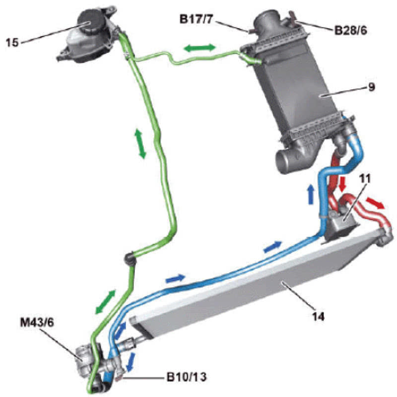
Finally, let’s examine the function sequence for charge air cooling. The charge air cooling maintains a charge air temperature of < 60 degrees C at 20 degrees C ambient temperature. This cooled air downstream of the charge air cooler has higher density, which means better cylinder volumetric efficiency and, of course, engine performance. The charge air cooler is liquid cooled, and is connected to the low temperature circuit via the low temperature cooler (radiator) and low temperature circulation pump. Inefficiencies in this system, or a failure, will affect the density and, therefore, the overall performance, which in turn can cause the control unit to detect deficiencies in the amplitude signals. The temperature is closely monitored by the engine control unit based on a voltage signal. Based on a mapped sequence, the ME-SFI will operate the low temperature circulation pump as needed.
Faults in the Field
Now that you have a grasp of the basic function of the turbo and its related components, we can take a look at some of the more common fault codes and symptoms you might encounter. Symptoms usually include a driver’s complaint of a lack of power or response, sluggish performance, or the vehicle doesn’t exhibit the same driving quality as before. These often will be accompanied by one or more of the following codes:
- P029900: The boost pressure of turbocharger 1 is too low. There is a mechanical fault.
- P029909: The boost pressure of turbocharger 1 is too low. There is a component fault.
- P029921: The boost pressure of turbocharger 1 is too low. The signal amplitude is less than the minimum amplitude.
- P023422: The boost pressure of turbocharger 1 is too high. The signal amplitude is greater than the maximum amplitude.
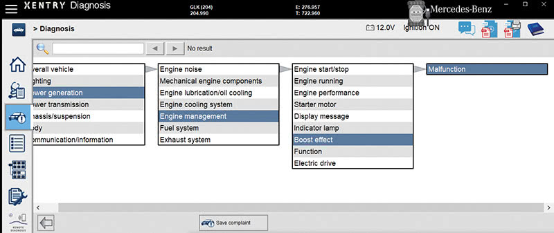
If you see any of these codes, and have a XENTRY Diagnosis system, then you are in luck, as it will guide you through a test plan. Here is an outline of what you need to check if you encounter these symptoms or codes.
It is important to check all of the charge air piping for leaks with smoke. Any leaks in the associated hoses and piping will result in an under-boost condition. Pressure testing the system with about 4 psi may be needed to find some leaks, so a high quality smoke machine is essential. Loose clamps, split or broken pipes or tubing are a common culprit. Sometimes, the problem may be as simple as a previous repair or service not completed properly. Also, be sure to check the integrity of the vacuum lines associated with the turbo controls.
Using your scan tool, verify that the pressure sensors upstream and downstream of the throttle (B28/6 and B28/7) are reading atmospheric pressure with the key on and engine off (KOEO). Since there is no boost happening with the engine off, they should read nearly identical. If not, then one of them is at fault and the engine control module just “thinks” it sees a boost problem. Pull and examine them for oil contamination, which can be a concern.
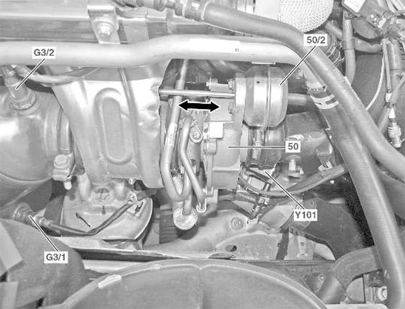
Hopefully, you have a scan tool that can activate the transducer. Using the actuation feature of the scan tool, you should be able to see the control rod move on the turbocharger wastegate diaphragm. Note: Do not force the rod by hand! If the rod doesn’t move, verify that Y31/5 (the Boost Pressure Control Pressure Transducer) can mechanically pass vacuum while energizing it. Be sure to use a gauge and not just listen for a click, as sometimes these valves will energize without allowing vacuum to pass.
A sometimes overlooked item is the actual vacuum produced by the vacuum pump. This can cause a failure of the vacuum solenoid or actuator of the wastegate. Check how much vacuum is produced at the vacuum pump small hose outlet. A new pump should produce about 28 inches (950 mBar). If the vacuum is low, then remove the vacuum pump cover and check for oil contamination. Specifications call for a minimum of around 750 mBar (11 psi).
After you have verified proper vacuum being supplied by the pump, check for similar vacuum at the inlet of the Boost Pressure Control Pressure Transducer Y31/5, referring to the vacuum diagram to find the right spot. If that’s low, then check for vacuum leaks along the vacuum circuit.
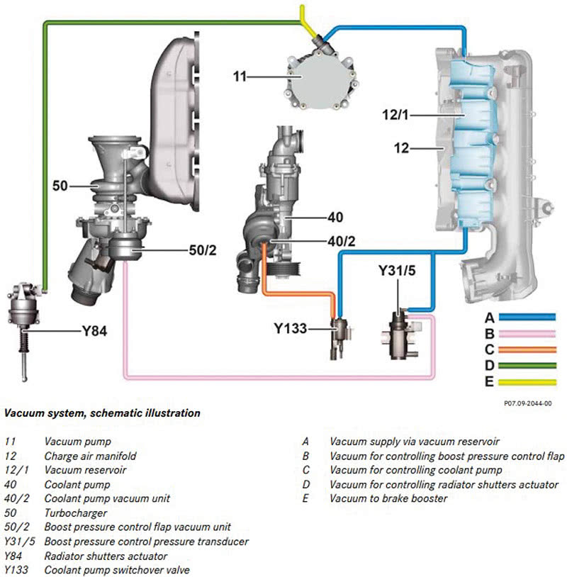
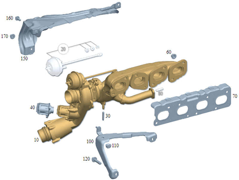
Check the diaphragm on the turbo wastegate vacuum actuator and make sure it can hold vacuum, and that the wastegate rod moves with vacuum applied from a vacuum tester. The rod should move at about 620 mBar (9 psi) and it should hold vacuum for at least a minute or so. Field reports have shown that a failure of the wastegate diaphragm is one of the most common failures of the turbo setting codes and not working properly, aside from vacuum leaks and bad connections. The wastegate on this particular model with the M274 engine does not come separately, and the whole turbo with manifold must be replaced. Looking at the ISPPI portal (the Mercedes-Benz parts catalog), there are some models that show it separate, but none of the ones we’ve seen in our shop. A quick call to your dealer should get you an answer.
Remember the bypass air switchover valve mentioned above? This can get stuck, and will need to be physically checked for proper operation, if you’ve narrowed down your diagnosis and eliminated other components. Granted, you should have a different code for failure of this component, but sometimes not. If you’re getting stumped on your diagnosis, don’t overlook this part. You may need to remove it to inspect it properly.
After going through all the above steps or the guided portion of your test plan, don’t overlook the obvious: make sure the turbocharger impeller spins freely. You can remove the intake ducting and (carefully) spin it and check for excess free play, but to inspect for damage to the exhaust side of the impeller you will need to insert a camera or borescope to verify the condition of the blades. Removing the exhaust down pipe should give you enough access for this operation.
Lastly, check for excessive exhaust backpressure. Too much, and your exhaust impeller can’t spool up fast enough to develop proper boost. This can be checked, typically with a gauge made with a fitting that uses a removed lambda sensor for access.
The Future
Just when you thought you knew your way around turbocharges, charge air coolers, wastegates, and vacuum systems, enter the electric driven turbo chargers! Newer models sport these—especially the AMG models. We expect to cover these some time in the future. Until then, we hope that this review of turbocharger technology and operations will help you serve your customers even better.


0 Comments