Is there any worse experience when finishing a complex automotive repair than to find a new problem, one that wasn’t there before, one that obviously came from something you just did? It’s hard enough when something goes wrong, some second unrelated problem in the course of a repair. Customers never believe it, of course, but at least you can feel some confidence yourself.
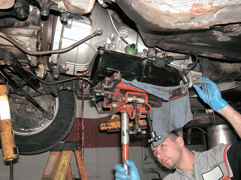
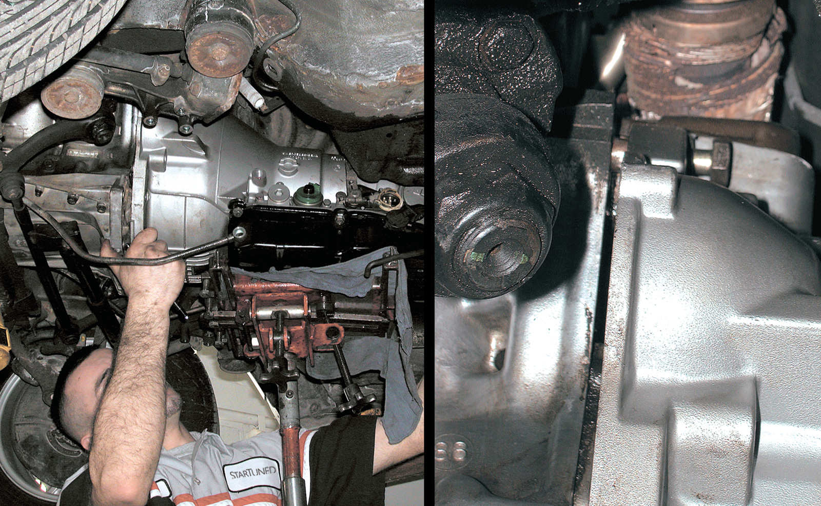
Drain the transmission both from the pan plug and (for most Mercedes-Benz vehicles) from a plug in the torque converter. Since this trans R&R was not chasing a trans problem but correcting a spark problem, the technician drained out only the minimum to keep the floor dry.
But if you replace a transmission because it is slipping in a 126 420, and then it doesn’t slip anymore but the car has no engine power, there’s not really any plausible story you can tell yourself that doesn’t involve your own work. So you push out whatever car you’re working on now and pull in the comeback. It’s not a happy story, but it’s part of automotive work. Tell me the number of people who say they’ve never had a comeback, and I’ll tell you the number of fibbers in the business.
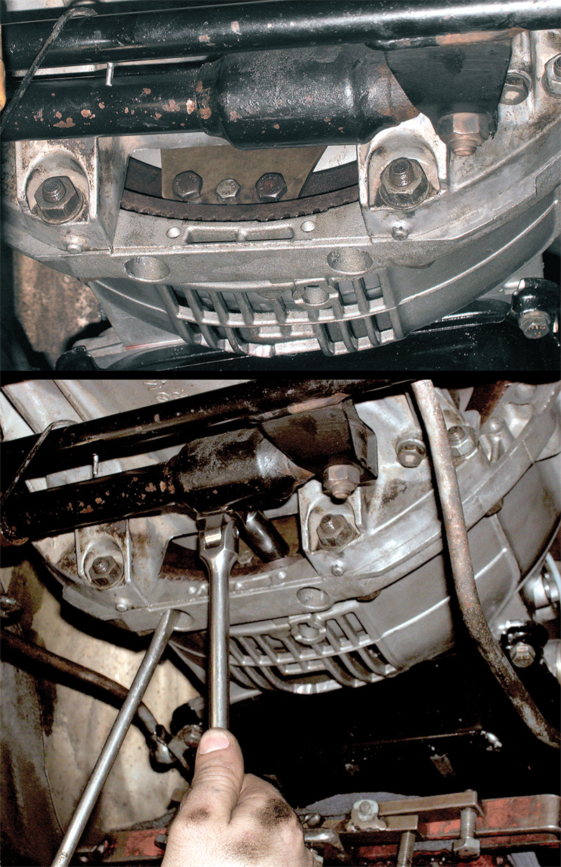
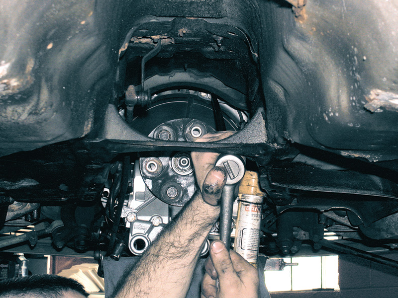
There are three sets of three hex heads as you rotate the flexplate. To unbolt the torque converter from the driveplate, loosen only the outer two bolts in each set. The inner bolts hold the ring gear to the flexplate. Be careful when rotating the flexplate to only turn in the normal direction of engine rotation, to protect the valve timing components of the engine.
A search of the service bulletins answered the question: There are three different positions you can bolt the ring gear to the flexplate. Two of them are wrong; one is right. Each of the wrong ones throws the crankshaft position signal 120 degrees out of place in opposite directions. Amazingly, the computer can make enough of a correction to the spark timing that the engine can still run. Service Bulletin 03/41, 15/35 spells this out with the warning, “When installing the ring gear and flexplates, care should be taken that the locating bores are aligned with one another. If, for example, the locating bores are offset by 120 degrees then the segments… on the ring gear will also be offset by 120 degrees with reference to the crankshaft. This will cause the crankshaft position sensor… to generate its signal at the wrong time and the electronic ignition control unit to compute the ignition timing incorrectly.” OK, there’s no easy way to correct this but to take the transmission back out, unbolt the flexplate, rebolt the ring gear in the right configuration and put everything back together.
So put the lift fingers under the lift pads. The car’s going up.But first disconnect the battery negative. Then withdraw the transmission dipstick and unbolt the dipstick tube bracket from the back of the cylinder head. Unsnap the control pressure cable ball and socket at the throttle linkage. You’ll remove the hook at the bottom of the cable, and it will possibly require readjustment when you put things back together. You’ll also unbolt the dipstick tube flange at the bottom as soon as you have the car airborne.
Unbolt and remove the transverse yoke. This is the part that connects the subframe between the steering gearbox and the idler arm pivot. Drain the oil from the transmission and from the torque converter.
Turning the ring gear clockwise from the front of the car, remove the two torque converter bolts from each of the three segments of the flexplate. Leave the center bolt for later; that holds the ring gear to the flexplate. Then being sure the engine will not pivot (a wooden wedge placed between the engine oil pan and the crossmember will work well), remove the exhaust system from the manifold to the tailpipe. If you can get this out as a unit, you can save some work, but you’ll need an assistant. Remove the exhaust hangers as well; you’ll need the clearance.
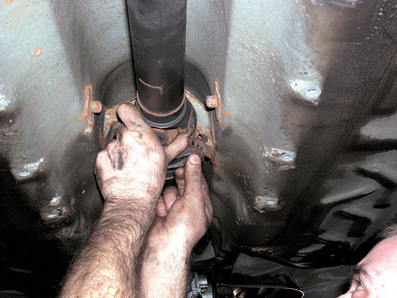
Match-mark the driveshaft and the transmission/differential flanges so you can insure the same balance as before. Make sure the center bearing is fully seated when you come to reinstall the driveshaft.
Then the heatshield protecting the driveshaft from the exhaust heat comes out, with all of its small perimeter screws. Then finally remove the driveshaft itself, with the bolts through the rubber bushings and the two bolts holding the center bearing. With its truly independent suspension, the Mercedes-Benz does not require universal joints to deliver torque to the drivewheels. The vibration-isolating rubber drive bushings usually last for the life of the car, but check them carefully anyway. It’s always a good idea to chalk-mark the driveshaft, the transmission output flange and the differential input flange in such a way that you can put them all back in exactly the same clock position.
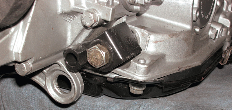
Next out is the rear engine mount, the one at the tailshaft of the transmission. With a support under the transmission pan to keep the engine/transmission pair from suddenly shifting, unbolt this first from the transmission housing and then from the chassis. Slowly release the support under the pan, making sure there is no sudden damage. Pay particular attention to the radiator fan and shroud. If the tailshaft moves far enough down, there could be interference between them.
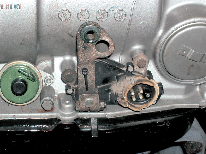
The neutral safety switch unplugs after it’s unlocked. Plastic bushings at either end of the shift rod can be replaced to snug the feel of the shift lever.
Next, you release the wires and shift linkage from the transmission. The neutral-safety switch simply unplugs once you pivot the lock sleeve upward. The linkage is most easily separated at the shift arm on the transmission, though it is good practice to remove it at the base of the shift lever as well so you can replace the pivot grommets with new ones. Doing so will snug up the linkage and prevent shift lever vibration at resonant frequencies.
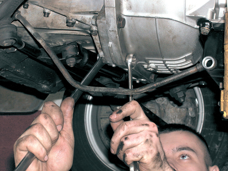
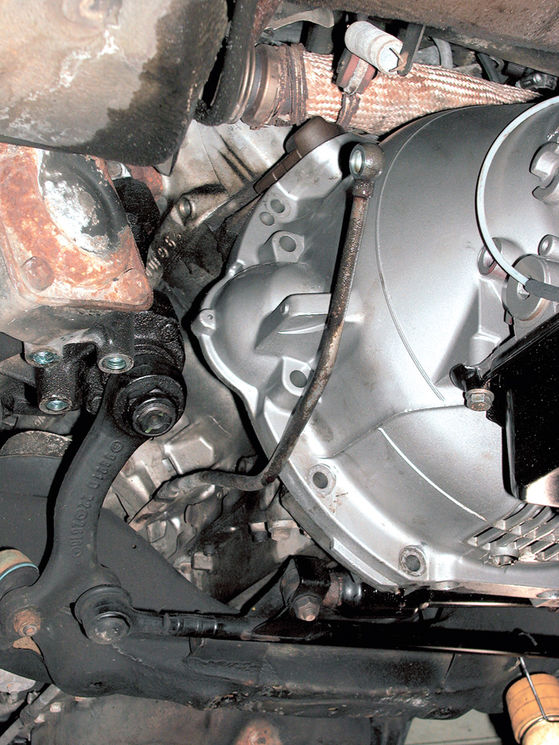
Loosen the banjo bolts on either side of the transmission, catching any transmission oil overflow from the coolant lines. Either at this point or when you’re putting the transmission back in, blow out the coolant lines with low-pressure shop air to confirm that the hydraulic circuit is unobstructed. Without free flow of ATF through these lines and the cooler in the vehicle radiator, a brand new transmission could overheat and fail in short order, so don’t skip this step. It’s better practice to replace the sealing washers on either side of the banjo bolt to insure that it’s leaktight. To provide enough clearance to get the transmission around the ends of the coolant lines, it may be worthwhile to release the tube clips on either side of the engine, held by oilpan screws and bellhousing clips.
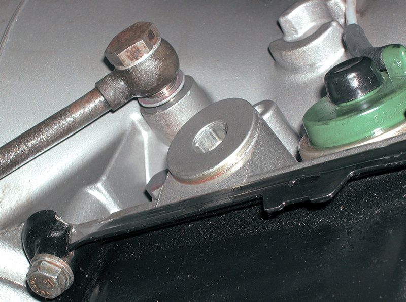
The transmission cooling system must work properly for satisfactory transmission life. Be sure to check that it is open from one end to the other and does not leak.
At the back of the transmission is the speedometer cable or vehicle speed sensor. You unplug it and loosen the cable ties holding its wire to the rear mount. Disconnect as well the vacuum modulator line from the back of the vacuum modulator, and notice whether there is any oil in the line. The presence of oil, of course, flags a damaged modulator diaphragm, which will adversely affect shift points and may cause smoke in the exhaust. Later model year transmissions included multiple vacuum lines to the modulator box.
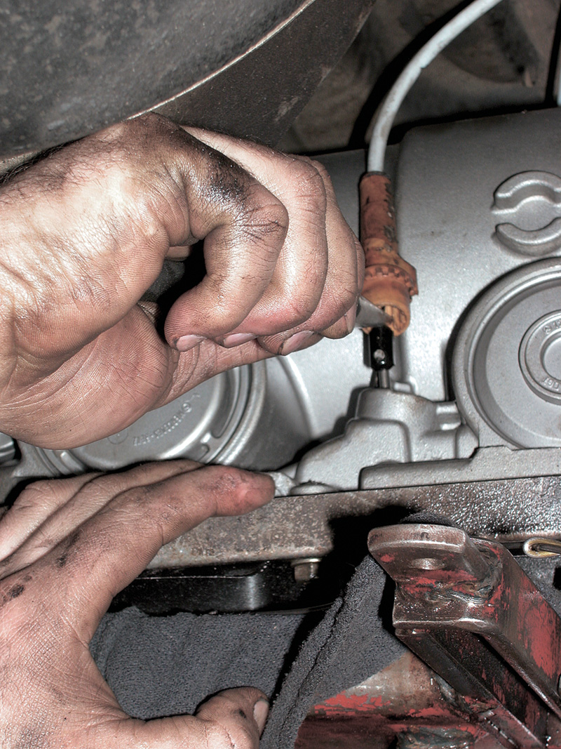
Don’t forget to release the control pressure cable. This control often requires readjustment once the cable is released from the transmission and (at the other end) the throttle linkage.
On the passenger side, lift the plastic fitting for the control pressure cable and release the hook. When reconnecting, you may need to use a hook to pull the cable down and needle nose to lift the hook again. When you’re working on top again, make sure the hook still engages the cable before you reconnect the balljoint at the linkage. On the passenger side rear, unplug the electrical connector for the kickdown solenoid.
Now to release the transmission itself from the engine. There are differing schools of thought about which sequence to use to release the bellhousing. It probably doesn’t actually matter, but I’ve always been partial to the theory that the uppermost bolts could hold the transmission alone, while if only the bottom ones were holding the weight, you might crack the lower casting.
If you buy my pitch, first remove the bellhousing through-bolts that also hold the starter. As you’re doing so, take care not to crimp the battery ground strap from the lower bolt, and make sure to position it so you’ll see it for sure on reassembly. Then go around the bottom of the ring, removing the bolts and nuts. Finally, remove them on opposite sides working toward the top middle. As you’re backing that last bolt or two out, wiggle things around a bit to confirm the transmission is resting securely on the trans jack (and the car balanced squarely on the lift!) and that everything will be out of the way.
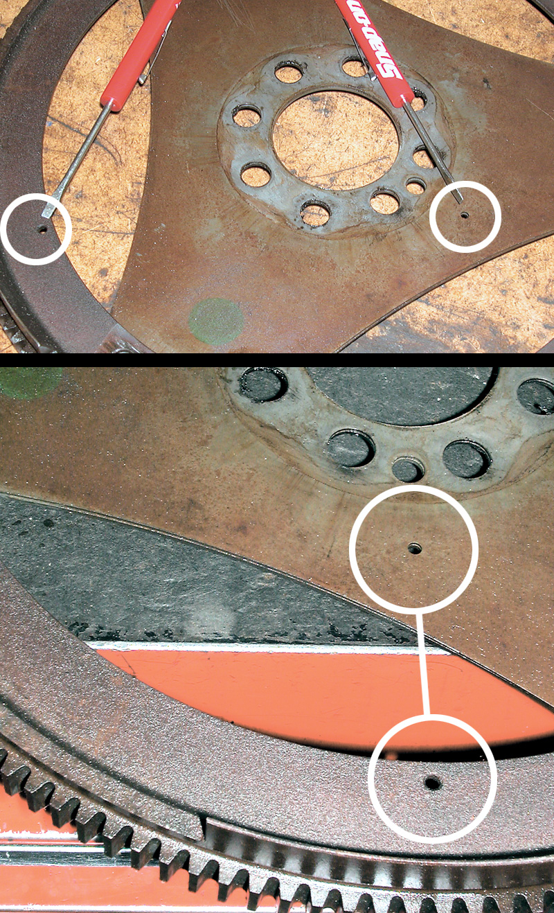
Hardly seems like a big deal, but it certainly did to the ignition computer. With the ring gear in the wrong clock position (screwdriver tips), timing was off by 120 degrees. The computer could make some correction, enough to get the engine running, but not enough to produce normal power. With the position corrected, the computer would know which cylinder was where.
This is one of those moments when your attention should shift to thoughts of personal safety. Should the transmission slip off the jack or should the torque converter jump out of the front pump, don’t try to catch it: Both are heavy, sharp, dirty and oily. What’s more, they’re replaceable parts. Your hands, feet and other ‘parts’ are not. Rock the transmission loose, making sure all wires, tubes and links are disconnected. Then slowly and carefully back the transmission up from the engine and lower it to a safe place.
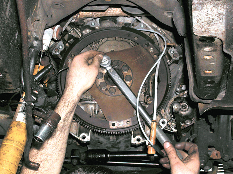
Torque each of the flexplate bolts (including those holding the ring gear!) in a starburst sequence, going around at least a second time to confirm that the stiffener plate and flexplate are bottomed against the crankshaft.
On this job, however, we weren’t after the transmission except to get it out of the way of the flexplate. The inner driveplate itself has a locator dowel, so it can only fit in one configuration relative to the crankshaft. The ring gear with the crankshaft position sensor segments, however, moves forward toward the engine to remove and correct its position, so we had to get everything on the workbench. There is a stiffener ring between the flywheel bolt heads and the flexplate. With the bolts out, reach behind the flexplate with a long prybar and gently walk the driveplate off the crankshaft end. Don’t let the locator pin jump out and escape.
With the flexplate and ring gear on the bench, the misalignment is clear enough. You simply remove the bolts and nuts fixing them together, reposition them in the correct alignment and retorque the bolts. Would have been quick work before, eh?
When putting things back together, there are a few heads-up points. Torque the flexplate and the ring gear attachment fasteners, with a torque wrench. While the specifications don’t require it, many shops also use a threadlocker on each of these fasteners because of their importance in the drivetrain. If you don’t torque them correctly, count taking this transmission out again, this time to replace the cracked flexplate. The same is true for the through-bolts to the torque converter.
As you’re lifting the transmission back into position against the engine, the tricky part comes with the locator dowels on either side of the bellhousing. These are quite the snug fit and must be correctly lined up before you can slide the transmission into place. If they are missing or removed, you’ll probably find a cracked flexplate fairly soon. Of course, the torque converter must also be properly bottomed in the pump recess.
There was a lesson in this (isn’t there always?). Murphy’s Law applies in Germany as well. Das Gesetz von Murphy, we might as well recognize, implies that if there are three ways of assembling something and if only one of them is right, that choice won’t occur its fair 1/3 share of the time. Matchmarking components as you disassemble them so you can get them back exactly as they were is one way to evade Herr Doktor Murphy. Another is to stop and get the relevant information if you find something that could be done in more than one way.
The fit between the engine, specifically the crankshaft centerline and the transmission input shaft centerline is very precise. Locator dowels on either side of the bellhousing insure accuracy of the lineup.




0 Comments