New technology keeps emissions far below legal requirements and improves fuel efficiency
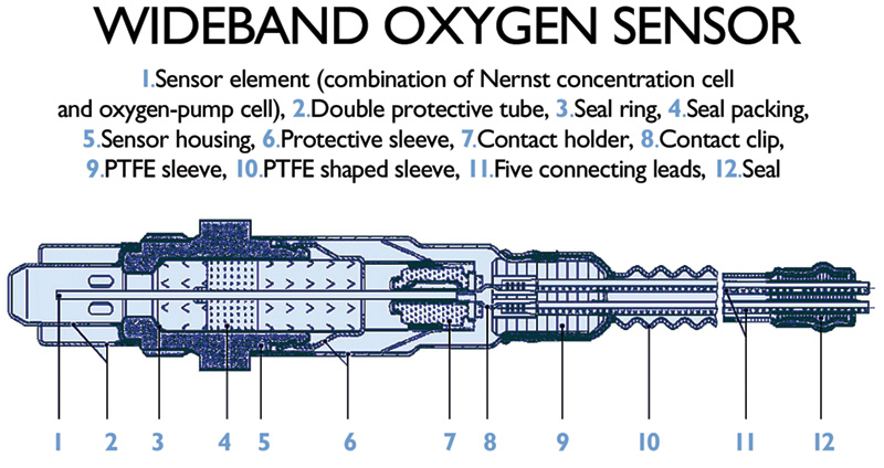
If you haven’t yet encountered the wide-band oxygen sensor, it’s time to get familiar with it. Here’s what it looks like inside. Note that the pumping cell allows it to produce a signal directly proportional to the air/fuel ratio, as opposed to the high and low switching of traditional oxygen sensors.
If you hear someone say “oxygen sensor†and the words “planar†or “wideband†don’t come to mind, you’ve fallen behind on oxygen sensor technology. The latest developments in oxygen sensors take air/fuel management technology to new levels of performance. And the new wideband sensors require new diagnostic techniques to identify potential problems.
In an ideal world, there would be no need for oxygen sensors. In theory, when you burn exactly one pound of gasoline using 14.7 pounds of air under optimal conditions, the gasoline burns completely. The technical term for the magic 14.7:1 number is the “stoichiometric” air/fuel ratio. At a constant stoichiometric ratio, the exhaust gas would contain only water and carbon dioxide (CO2). Yes, carbon dioxide is considered one of the “greenhouse gases†that may contribute to global warming. So the exhaust could still be considered a pollutant. But in our ideal world, emission control would consist of primarily of capturing the water and carbon dioxide and storing the mixture in a seltzer water dispenser! Actually, the two are what plants need to grow.
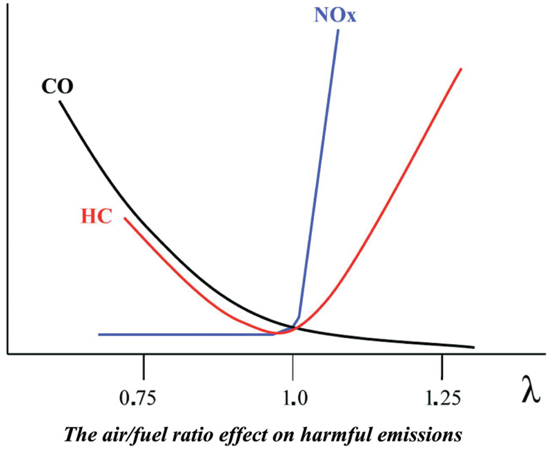
Here’s how exhaust gas emissions rise and fall in relation to the Lambda value. Generally, emissions increase whenever the mixture is not stoichiometric, which air/fuel ratio is represented by the number “1”.
But the internal combustion engine never operates in an ideal world under optimal conditions. And even minor variations from stoichiometric cause major increases in various pollutants, as the chart below shows.
Lean mixtures do improve fuel economy, but at the expense of a greater output of oxides of nitrogen (NOx), and unburned hydrocarbons (HC) if they are lean enough to cause misfire. Rich mixtures not only hurt fuel economy, but also increase CO emissions (which are incompletely burned fuel molecules) and HC.
As the level of oxygen in the exhaust gas changes, output voltage from the oxygen sensor changes. The change in signal triggers the engine control module (ECM, or PCM for Powertrain Control Module, the SAE term standardized under J1930) to lean out or richen the fuel mixture to keep combustion as close to stoichiometric as possible.
Robert Bosch introduced oxygen sensors in 1976 as a key component of the revolutionary Lambda-Sond fuel injection system, and Mercedes-Benz was among the first carmakers to adopt this advance. The sensor continually monitored the amount of oxygen in the exhaust stream. The output voltage signal it sent to the engine controller changed as the oxygen level changed. When a lean condition (too much oxygen) was detected the output voltage dropped, triggering the engine controller to richen the mixture. A rich condition increased sensor output voltage, which prompted the controller to lean the mixture. Sensor and controller worked together, creating a “closed loop†system that automatically regulated engine operation.
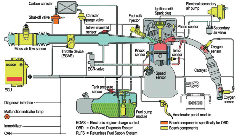
This OBD II-compliant Motronic system shows just how much is involved in modern engine management. Regardless of all the recent developments, however, oxygen sensors remain the linchpin of accurate air/fuel mixture control.
Initially, Bosch called its new sensor a “Lambda sensor” because the oscilloscope curve tracking sensor voltage output to oxygen levels in the exhaust resembled the shape of “Lambda,” the 11th letter of the Greek alphabet.
You will also hear the term “Lambda value†when engineers talk about combustion and exhaust gas analysis. At 14.7:1, or stoichiometric, Lambda is one. When the mixture is lean, more than 14.7 pounds of air to one pound of fuel, Lambda is greater than one. Rich mixtures (less than 14.7 pounds of air for one pound of fuel) Lambda is less than one.
In the 30 years since oxygen sensors and closed loop systems were introduced, electronics and computer controls have grown so sophisticated that even the least expensive new car has more onboard computer power than the NASA space craft that placed a man on the moon! However, despite all the changes in automotive electronics, one thing has remained constant—the oxygen sensor is the most critical component in controlling vehicle emissions.
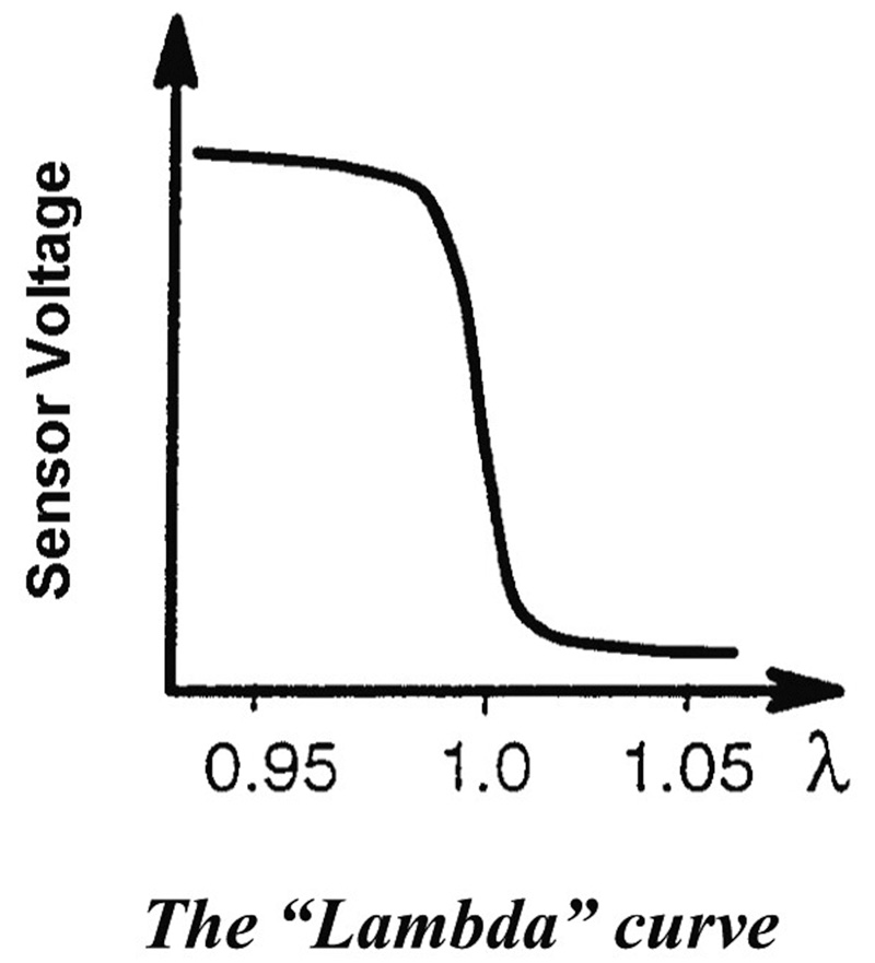
In a regular oxygen sensor, output voltage changes dramatically as the air/fuel mixture crosses the Lambda line. Remember, “lean equals low.”
The ECM is constantly bombarded with input from sensors located throughout the car. But the ECM “listens†to the oxygen sensor first and adjusts the air fuel mixture based on the sensor’s output signal.
Modern oxygen sensors are so valuable to engine performance, even race cars, which are not required to comply with emission standards, use them to maximize performance. You will find oxygen sensors not only on sophisticated racers, like the ALMS GTS class, but also on NASCAR racers with their pushrod V-8 engines and quad carburetors. Some NASCAR teams mount eight sensors on an engine, one for every cylinder, to get optimal fuel distribution from the single carburetor.
Almost all of the oxygen sensors in use are from one of four generations of technology. A very small number of cars, estimated at less than 0.5% of the vehicles now on the road, use a titanium oxygen sensor. This technology doesn’t fall within the four generations, but you don’t have to worry about this sensor because the design was never used by Mercedes.
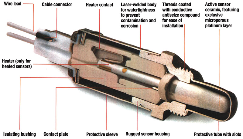
The ceramic thimble with its metallic coating actually acts as an electrical cell. The difference in the oxygen content of the reference air to that of exhaust gas is what generates voltage.
For 99.5%+ of the cars on the road today, the oxygen sensor will be in one of the following generations:
•“Unheated thimble” and “heated thimble†sensors were the first two generations. “Thimble†refers to the shape of the sensor tip, the portion that actually measures oxygen content. Unheated sensors were used from the late 1970s until the mid 1990s, although the heated design began to replace unheated in the early 1980s.
Unheated thimbles were adequate for early emission standards, but as their name implies, unheated thimbles did not start sensing oxygen levels until warmed up by the exhaust gas. During the critical engine start and warm-up phases when emissions are often very high, these sensors couldn’t send a signal to the computer. Unheated thimble sensors also have a relatively short service life, often requiring replacement as often as every 30,000 miles.
Heated thimble sensors first appeared in 1982 and gradually replaced the older unheated design. To reduce emissions during starting and warm-up, an electrical heating element inside the sensor brings it to operating temperature much faster than its unheated counterpart. Heated thimble sensors were state-of-the-art until the introduction of the heated planar sensors in the late 1990s.
- Heated “planar” sensors were first used in the United States in 1998 and represent the first major redesign of oxygen sensors since the original unheated thimbles. A heated planar oxygen sensor is fully active and providing output signals to the engine computer within a few seconds after engine start, helping to reduce start-up/warm-up emissions.
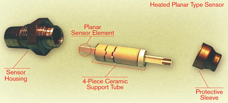
The planar type, which first appeared in 1998, uses a much lighter unified strip to produce voltage instead of that big thimble. With its integrated heater, it starts sending the PCM accurate signals almost immediately upon start-up.
Instead of the ceramic thimble, heated planar sensors utilize a flat ceramic zirconia element, less than two millimeters thick, projecting into the exhaust stream. The electrodes, conductive layer of ceramic, and heater are laminated into a unified layered strip. This strip is smaller, lighter, and more resistant to contamination than the thimble design. The planar sensor’s integrated heater element also requires less electrical power to reach operating temperature. That is a real advantage when you consider the number of amps necessary to bring a heated thimble type up to the 600 deg. F. required.
Because of their superior performance, heated planar sensors are now found on nearly 50 percent of all new vehicles. Planar sensors send oxygen level signals to the onboard computer five to seven times per second for much more precision in fuel management. To put this into historical perspective, the O2 sensors used on cars with feedback carburetors sent only one signal per second, and those used with throttle body injection provided only two to three signals per second.
In some applications, you can upgrade an older heated thimble sensor to a heated planar, but you can never go downscale — you cannot install a thimble sensor to replace a planar.
- Heated Wideband Sensors are the latest in oxygen sensor technology. This sensor upgrades the planar sensor’s layered ceramic strip by adding a “pumping cell.” The pumping cell allows the wideband sensor to produce a signal directly proportional to the air/fuel ratio instead of simply switching rich to lean at the 450 millivolt threshold. These heated wideband sensors operate at about 1,400 degrees F. (700 to 800 degrees C.), twice as hot as older designs. And they reach this temperature within 20 seconds after a cold start. Response time to changes in air/fuel ratios is less than 100 milliseconds, much faster than any previous sensor for optimal management of the air fuel ratio.
Heated Wideband oxygen sensors solve a major shortcoming of previous generation sensors. Although the early sensors responded to changes in oxygen level, the sensors did not truly “read†the exact level of oxygen. Instead, their voltage output simply shifted as the mixture moved back and forth between “too rich†and “too lean.â€
At stoichiometric, when the air/fuel ratio is perfectly balanced, conventional sensors have an output voltage of about 0.45 volts (450 millivolts). When the fuel mixture goes even a little rich, the sensor’s voltage output doesn’t increase slightly. It shoots up to its maximum output of about 0.9 volts. When the mixture is lean, sensor output voltage quickly drops to 0.1 volts.
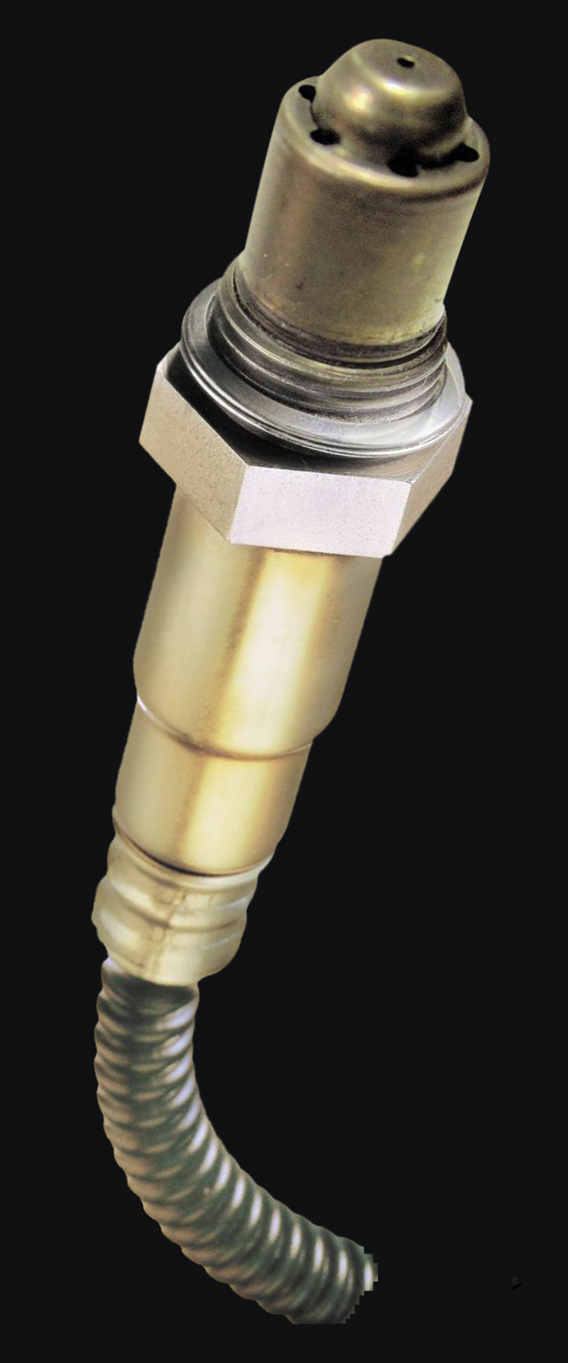
Although it may look very similar to a planar sensor from the outside, the wide-band type sends a completely different kind of signal to the computer, which results in much more accurate mixture control than can be achieved with the “dithering” of a regular thimble or planar oxygen sensor.
Every time the oxygen sensor’s output jumped back and forth, the engine computer responded by decreasing or increasing the amount of fuel delivered to the combustion chamber. The rapid flip-flopping by the sensor and the onboard computer tended to achieve something approaching “an average†stoichiometric condition. But averaging stoichiometric is not good enough for the latest emission control standards.
The new NLEV (National Low Emission Vehicle) standards, California’s LEV (Low Emission Vehicle), ULEV (Ultra Low Emission Vehicle) and SULEV (Super Ultra Low Emission Vehicle) standards require more precise control over air/fuel ratios than thimble and planar sensors can provide. The earlier sensors don’t reach operating temperature fast enough, even those with a built-in heating unit. And no previous sensor type can send a precise voltage signal to the computer in response to minor changes in Lambda value. The wideband oxygen sensor overcomes these problems.
The wideband sensors provide precise readings for air/fuel ratios from super rich (Lambda 0.7, or an air/fuel ratio of about 11:1 — what you might see in a drag racer) to pure air (all air, no fuel). The wideband oxygen sensor receives a reference voltage from the engine computer and generates a signal current that varies according to the fuel mixture.
When the air/fuel mixture is perfectly balanced at 14.7:1, the wideband sensor produces no output current. As the air/fuel mixture starts to go rich, the sensor output goes from zero to about negative 2.0 milliamps. The maximum rich reading occurs at Lambda 0.7 (the 11:1 air/fuel ratio already mentioned, which is the borderline limit of a combustible mixture — any richer and the charge would not burn). When the air/fuel mixture is lean, the sensor produces a positive current that goes from zero up to 1.5 milliamps as the mixture becomes close to pure air.
Basically, the wideband oxygen sensor adds an “oxygen pump†to a planar sensor. This pump pulls a sample of the oxygen in the exhaust into a “diffusion†gap within the sensor. The sensor is designed so that a certain amount of current is needed to maintain a balanced oxygen level in the diffusion gap. The amount of current needed to maintain this balance is directly proportional to the oxygen level in the exhaust. This gives the engine computer the precise air/fuel measurements it needs to meet the new emission requirements.
Wideband Sensor Diagnostics
Wideband oxygen sensors and planar sensors should last up to 100,000 miles unless subject to some type of abuse, such as excessive oil consumption, or silicone sealant contamination. Although rare, sensors can be damaged by using poorly refined gasoline. An exhaust leak large enough to allow water, road salt, or dirt into the system can also damage a sensor.
Oxygen sensors don’t die young from ordinary use; they are killed by something out of the ordinary. Be very suspicious of any oxygen sensor that fails far sooner than its expected service life. If you don’t identify and correct the basic fault, the replacement sensor will soon fail also, just like the original. Not only will you be faced with a comeback for the cost of installing another sensor, you may have a tough time getting your customer to pay for the repair that you missed the first time.
Symptoms of a damaged wideband sensor are the same as those for any oxygen sensor:
- MIL light or code set.
- Failed emissions test, usually with a high CO and/or a high HC reading.
- Damaged catalytic converter caused by prolonged exposure to an overly rich fuel mixture.
- Drop in fuel mileage attributed to a rich fuel mixture.
- Engine performance complaints such as “runs rough†or “sluggish.â€
Unlike earlier sensors, you cannot use a voltmeter or oscilloscope to diagnose a faulty wideband oxygen sensor. A wideband sensor’s output signal varies in both amplitude and direction. The only way to monitor a wideband sensor’s operation is with a scan tool hooked to the onboard diagnostic link.
With the scan tool in place, you can read the actual air/fuel ratio and check the sensor’s response to changes in the ratio. For example, going to wide-open throttle typically causes a brief very lean condition, followed by a rich condition. With the wideband oxygen sensor’s rapid response capability, the scan tool should show a steady air/fuel ratio (as long as the sensor is operating properly).
You must consult the specific diagnostic steps for the model you are working on, but as a general rule, your scan tool should show an oxygen sensor code if the sensor reads out of its normal range, if the readings don’t make sense to the computer (should indicate lean when lean conditions exist, etc.) or if the heater circuit fails.
Even wideband oxygen sensors can be fooled, just like other oxygen sensors, if there is an air leak between the exhaust manifold and head, or by a misfire that dumps an unburned air/fuel mixture into the exhaust. These situations cause a false condition that, in turn, signals the computer to mistakenly adjust the mixture.Â


0 Comments