Subtle troubles can occur if those diodes are leaking
Editor’s Note: We’re aware of the preference for the term “generator” in some quarters, but we believe “alternator” makes a useful distinction — Mercedes-Benz vehicles tend to last so long that there are still many on the road that have actual DC generators.
Got a vehicle with mysterious electrical problems? Too much ripple in an alternator’s output can cause electronic modules to misbehave, along with all sorts of other problems. Modules may reset, self-trigger, or misinterpret sensor readings when they’re not supplied with good, clean power, or are getting hit with excessive EMI (electromagnetic interference).
Measuring alternator ripple is a quick and easy test to perform. It should take under a minute, depending on how challenging access to the alternator is, and the results can warn you of potential charging system problems. In this article we’ll discuss the best ways to check ripple, the correct tools to use, and what you should be on the lookout for.
DMM and lab scope
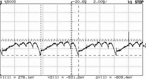
You can quickly test for ripple with a Digital Multimeter (DMM) set on AC volts. With the engine running at 3,000 rpm and the headlamps on low beam, attach one lead to the alternator B+ terminal and the other to the alternator case. If the AC voltage exceeds .5 volts, you may have a rectification problem. An oscilloscope provides even better diagnostic information. Probing these same points with an oscilloscope will display the “mmm†or “picket fence†pattern of working diodes, or the “tails†and other irregular patterns caused by failed diodes or windings. Mercedes Repair Document 15-0600, “Checking Alternator with Regulator In Vehicle†illustrates “good†and “bad†patterns.
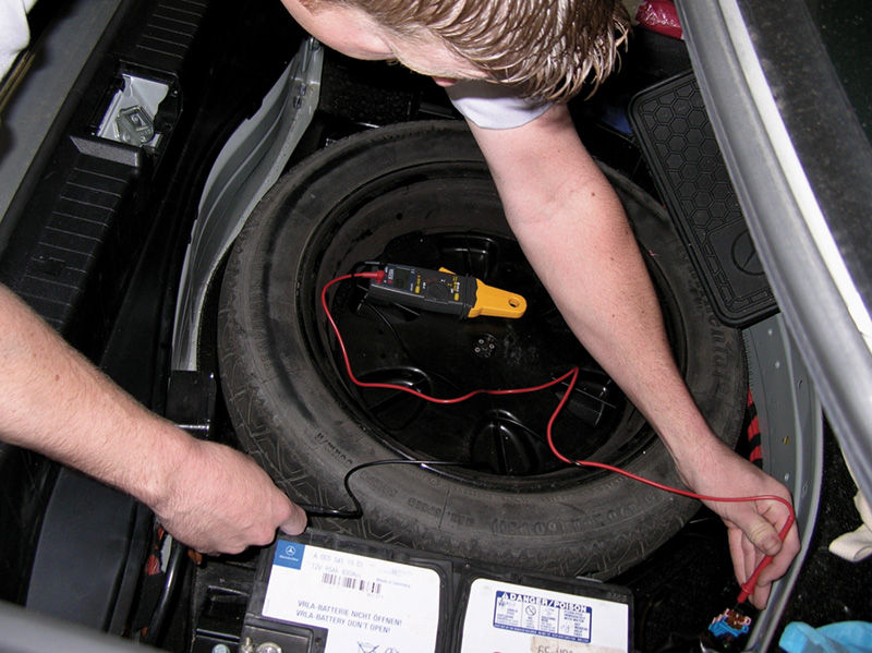
Where you measure ripple is as important as the tools you use to do it. The vehicle battery acts like a gigantic capacitor, smoothing out alternator ripple. The closer to the source of the noise — the alternator — the more accurate a measurement you’ll get. Ideally, you want to place your scope leads on the alternator B+ terminal and against the alternator case itself.

A measurement of ripple at the battery terminals won’t be as accurate as taking it at the alternator.
Failed load test
Alternator ripple is electrical “noise” that is produced during the rectification of the three-phase alternating current produced by the alternator into direct current. It increases significantly when rectifier diodes, windings, and other alternator components fail. Since load testing an alternator will conclusively confirm the presence of bad diodes or failed windings, the value of measuring or viewing ripple exists mainly as a quick test. A bad diode will cause 33% of the alternator’s current output to be lost, something you can’t miss performing a load test. Even so, an understanding of ripple will benefit the technician combating mysterious electrical or electronics problems, and charging issues.
A failing alternator diode will not only contaminate the power supplied to the vehicle with ripple, it can also “spray†electromagnetic interference, which can trigger ignition systems, falsify sensor readings, and give a hard time to keyless entry and other radio frequency (RF) systems. EMI can also generate static on the radio, produce alternator whine, and interfere with cellphones, broadband internet, and other radio systems.
Traces
Viewing the alternator output with an oscilloscope is the preferred technique for diagnosing ripple. If an alternator is suffering from a diode fault, long downward “tails” typically appear from the trace at regular intervals. The amplitude of the waveform will vary under different conditions. A fully charged battery will show a “flatter” picture, while a discharged battery will show an exaggerated amplitude. Be careful about fluorescent drop lights — having one too close can create false readings on your scope.
In addition to battery charge level, alternator design itself affects the amount of ripple produced. Heavy-duty eight and 12 diode alternators will produce more ripple than six diode units. In general, the higher amperage, more powerful alternators used in larger vehicles will generate more ripple. This can be up to a volt or more when heavily loaded. Consequently, a look with an oscilloscope will generate fewer “false positives†than a simple measurement with a DMM. Part of the problem with measuring ripple with a DMM is that averaging and “true-RMS†meters alike assume that users are attempting to measure a sine wave and calculate an AC value based on that. If you are measuring a non-sinusoidal waveform (i.e. spiky with a bad diode), the meter can display false results; in some cases, wildly wrong. Hence the preference for using a scope. If you have an alternator that is putting out a voltage that swings sinusoidally between 12.5 and 14.5 volts, you’d have a DC component of 13.5 volts, and an AC component of 1.0 volts effectively “riding on top” of the DC component. Depending on the voltmeter you used, whether it was a true RMS or an estimating type, it might read .7V AC or 1.0V AC. A capacitor inside the DMM is used to filter out the DC component when the meter is set to make AC readings. Similarly, on an oscilloscope this is known as“AC Coupling†since a capacitor effectively blocks any DC current from flowing.

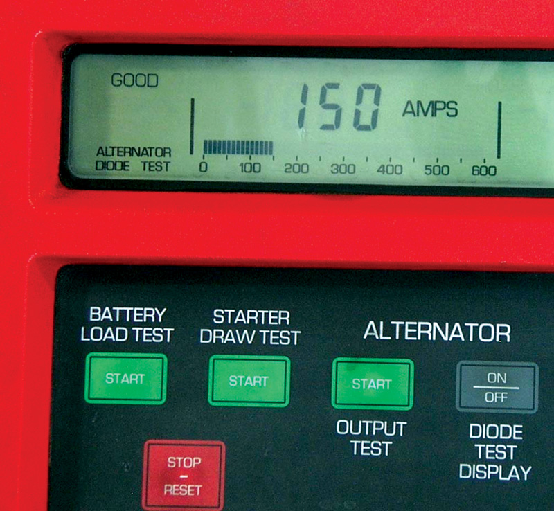
Most VATs include a ripple function. This one reads out the actual AC content instead of just turning on a warning lamp.
Always some AC
What an alternator puts out, even after it is “rectified†by the diodes (that is, converted to DC), isn’t very pretty. Even a healthy alternator puts out some ripple. And it won’t produce AC readings on voltmeters that are nearly as accurate as a “pretty†sinusoidal waveform would. An old-fashioned analog type voltmeter with a needle might in fact give more accurate readings of AC ripple than a modern DMM, because the inertia of the needle itself “averages†the signal somewhat, and your eyes can do the rest. As one M-B specialist technician says, “I have found that using an AC volt meter to be a waste of time to test for AC ripple on vehicle generators. The AC volt meter voltage depends a lot on the shape of the waveform, and most times AC noise from the generator does not resemble a clean sine wave.”
Another M-B tech tells StarTuned, “Even a properly functioning alternator generates some ripple. The ‘picket fence’ pattern of a properly functioning rectifier bridge includes some AC energy. The question is, ‘How much?’ Often, the picket fence pattern may look okay, but the total amplitude is unacceptable. Other times, with a truly failed diode, one or more ‘pickets’ will be missing, or there will be spikes/hash/noise accompanying the pattern of an excessive magnitude.”
The typical VAT (Volt Amp Tester) includes diode testing features. These are usually also measuring the amount of AC energy being produced, and the warning light may trip at somewhere between .25 and .5 volts of AC. On one common model, for instance, a partially discharged battery may indicate “Diodes Marginal,†while it will indicate that everything is fine if the battery is fully charged.
Clearly, looking at the alternator output with an oscilloscope is the best technique for analyzing ripple. The three-peak pattern of good diodes is unmistakable on a scope readout, and so is a two-high, one-low pattern of an alternator with a single failed diode. Even using a scope, the pattern you see won’t be as “pretty†as what is shown in textbooks where patterns are obtained from alternators that aren’t connected to noisy loads. If you don’t know how to use an oscilloscope, checking alternator ripple is the ideal task to learn on since it’s as simple a scope task as there is.
Specifications for the maximum permissible amount of ripple vary. In general, with older carbureted vehicles, anything under two volts peak-to-peak was okay; no sensitive electronics were aboard. On early fuel injected cars, generally under one volt peak-to-peak was acceptable. But on later models, nothing more than .5 V is acceptable. It’s typically when one or more diodes begin to break down, and allow current to flow in both directions, or neither, that AC ripple increases, and strange electrical problems begin. Remember, ripple propagates all the way through the vehicle’s electrical system.
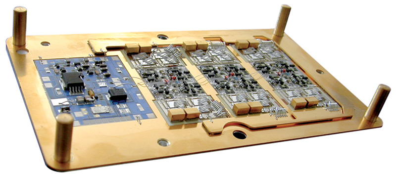
| The Future of Alternator Ripple Alternator ripple may look a lot different in the future. Literally. In today’s alternators, diodes are used to rectify the windings’ output by only allowing current to flow in fixed directions in order to exit the rectifier bridge. For this service, diodes charge a hefty price; a voltage drop of .6 to .7 volts. That voltage drop generates significant unwanted heat. Tomorrow’s alternators will use field effect transistors – FETs – to switch the current flow between two paths without the heavy penalty imposed by diodes. So-called “Active Rectification†can provide a 25% boost in power output from a standard alternator. The ripple pattern active rectification will produce will look entirely different. The first production “Active Integrated Rectifier Regulator” was designed by International Rectifier for the alternator in the Maybach and provided an astounding 350 Amps at 6,000 rpm (cold), and more than 200 Amps at idle. Some future Mercedes-Benz vehicles will be equipped with Integrated Starter/Alternator Devices, or ISADs, which combine the function of the starter and alternator. Some may be belt driven, while others will be mounted inline between the engine and transmission. ISADs can provide torque smoothing, eliminating the need for a dual-mass flywheel in diesel applications. ISAD’s will benefit from AR technology just like any other AC generator. |
Â


0 Comments