
After pulling off the engine cover, but before removing the coil, a quick scope pattern of the coil primary circuit will indicate if the coil is being commanded to fire, and also give an indication of the quality of the spark.
The coordination of ignition, fuel delivery and basic engine function is required before internal combustion can take place. Here, we’ll look at the ignition system from its basic function and proper operation to advancements made by BMW to reduce maintenance, decrease emissions and increase performance.
For whatever reason, when a “no-start†condition was encountered the first test traditionally performed was usually that for ignition output. Maybe it was the ease of the test, or that the carburetor, working on natural principles, would be expected to supply fuel. As long as the engine sounded like it was turning over normally, the “spark test†was as simple as pulling a plug or coil wire, holding it ? inch away from ground and cranking. If you were smart, you used a test plug to avoid any shocking personal involvement in the process. Today, however, this test can be time consuming because of engine covers, bolted-down coils and involved spark plug access. In order to remain efficient and profitable we must develop faster methods of determining if we have sufficient spark to ignite a compressed air/fuel mixture. When it comes to misfires, we also have to judge the quality of the spark. Of course, anything from fuel quality and proper mixture to basic engine compression can cause a misfire, but we need to be able to determine if spark is the cause of the problem.
A brief history of spark distribution
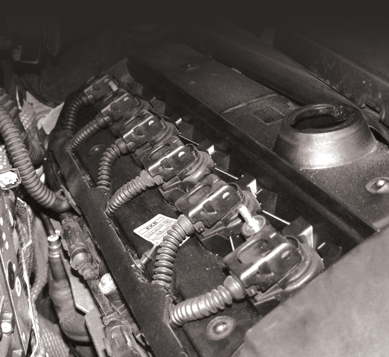
Here’s a typical BMW coil-over-plug setup. These coils are capable of putting out 30 to 50kV. You can see the self-contained plastic housing for the coil primary wiring.This is where the shunt resistor resides
Before electronics took over, we had “breaker point†ignition. A mechanically-driven distributor would spin a cam that opened a set of points against spring pressure. When the points were closed they completed the circuit through the primary winding of the ignition coil, which created a magnetic field, the duration of which was called “dwell.” When a cam lobe pushed the points open, the field would collapse generating high voltage (15kV or so) in the secondary winding of the coil. Spark became available at the coil tower and would then pass through the rotor and distributor cap and continue on to the spark plugs.
With the advent of electronic ignition, a module was used to control coil dwell and was commanded either directly by a “pick-up,†or by a control unit using crank and cam position sensors. In the case of older BMW vehicles, the Bosch Motronic control unit would receive the sensor signals (both reference and TDC) and directly control the dwell and firing time of the coil. The use of electronic control increased the output of the coil to about 28kV. In 1992 on certain models, BMW started using individual coils to fire each spark plug separately. Each coil is directly controlled by the Digital Motor Electronics unit (DME). These coils are capable of producing 30 to 50kV. Another benefit of individual coil control is the DME’s ability to manage coil dwell and timing in response to engine load signal, knock sensor inputs and ignition monitoring feedback.
What, Where, When, Why and How?
How does the DME unit know when to fire the coil? Obviously, it must know the position of the crankshaft in order to determine the proper ignition advance for each cylinder. Before the mid-1990s, two crankshaft sensors were used. One was called a TDC (Top Dead Center) sensor and the other was known as the reference (Speed) sensor. Both were mounted in the bell-housing of the transmission. The TDC sensor would inform the Motronic control unit as to when the Number One cylinder was coming up to top dead center. The Reference sensor would read the teeth on the flywheel or flex-plate to indicate how fast the engine was spinning. The Motronic unit would fire the single coil and the coil wire would pass on the induced spark to the distributor cap and it would then continue on to the cylinder.
With this system, the distributor cap, rotor and spark plug wires, along with the plugs themselves, would periodically be replaced in a tune-up. Since BMW has moved on to a coil-over-plug design, the parts that used to channel high voltage have been eliminated.
With individual coils for each cylinder, the DME control unit must also know the position of the camshaft in order to determine if the cylinder is under compression or exhaust. This is not a waste-spark system where a single coil provides spark to a cylinder under compression and another under exhaust! The DME fires each coil according to a preprogrammed map using various inputs from sensors on such things as coolant and intake air temperature and mass airflow. The crankshaft position sensor is critical to spark control, and the DME will not attempt to fire the coils without it. The camshaft position sensor is also important, but on coil-over-plug applications the engine will start without this signal, but will run poorly. The symptom even applys to later vehicles — more on this later.
So, ignition control is determined from the internal map from a properly powered-up DME control unit and inputs from the crankshaft and camshaft position sensors. The DME in turn grounds the appropriate coil to saturate its field until it opens the circuit, which causes the field to collapse and provide a spark. So far we have answered What, Where, When, Why but we have not answered How.
And How!
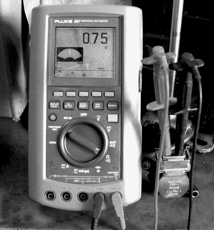
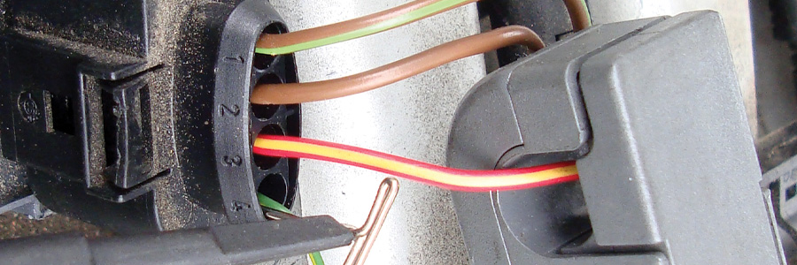
This is often the first test performed on a coil — the static test of primary winding resistance, measured across the two outside pins of the three-pin connector. Remember, just because a coil passes this test does not mean it is actually functioning.
As mentioned earlier, since the inception of the Motronic control unit, the coil(s) has been controlled directly. On the ‘92 318 (E36), BMW used a coil pack and plug wires, but this was abandoned by ‘94. Coil-over-plug became the preferred method of ignition. Not only was timing controlled on an individual cylinder basis, but so was the amount of coil current. The way BMW powers up its coils has changed also. Since ’97, the power supply for the multiple coils is from an ignition coil relay otherwise known as an “unloader relay.†Since the relay provides power, the current does not have to pass through the ignition switch, thus reducing its electrical load.
BMW uses two manufacturers for its coils, Bosch and Bremi. The coil specifications are essentially the same, however. Coil resistance on the primary winding is about .5 ohm previous to 1996. For ’96 (’95 for the 4.0L engine), the coil primary resistance increased to about .8 to 1.0 ohms (measured between the two outer pins of the coil). The center terminal of the coil is wired from ground through a “shunt resistor†and is connected to the secondary winding. This resistance is too high for most ohmmeters to measure. The only measurable difference between the Bosch and Bremi coils is the resistance of the extension boot out of the secondary tower. The Bosch coil is about 1K ohms and the Bremi boot is about 1.8K ohms.
How are we going to test it?
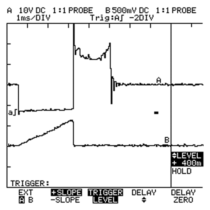
Watch the top pattern and you’ll see the pull to ground, the inductive kick and the burn time. This shows that adequate spark took place. The lower waveform is the current pattern of the same coil. The low current probe was set to 100mV per amp. Just over one 500mV per division means over 5 amps are being produced. Compare to other cylinders, or previous test results.
If you have a no-start and you want to check for spark, you do not have to remove the coil and install a HEI (High Energy Ignition) spark tester. Instead, you can remove the coil cover and scope the coil primary trigger. You will see a typical coil primary pattern — the initial pull to ground followed by the inductive kick or “spike†of the coil’s ground being released, the “burn time,†and finally the coil oscillations. If you see a pattern without the pull to ground, inductive kick or burn time you do not have sufficient spark. If the vehicle is starting, but you feel you may have an ignition-related misfire, monitoring coil primary will probably not be enough information to lead to a diagnosis.
The first step is typically the primary and secondary resistance test. This is a “static†test, which means you are testing the component outside of the operating system. A resistance test will tell you if you have a bad coil, but it will not tell you if you have a good one. That is, if the resistance values are within specification that does not guarantee that we have a good coil.
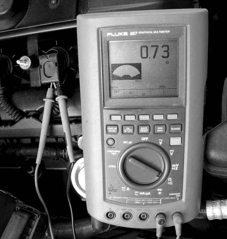
You do not have to remove the coil to determine its resistance. Back-probing the terminals will suffice. Remember, before ’95 resistance of the primary winding is .45 ohms, and after ’96 it’s about .8 ohms.
Another method of evaluating a coil’s performance is monitoring its current draw. This is known as a “dynamic†test. The test is performed while the coil is operating in the system. This can be achieved by using a low-current inductive probe around the coil power feed or ground trigger wire and watching the “current ramp†on a scope. The rate at which the coil builds current and its peak current are critical to determining if the coil is functioning properly. You can look at a known-good pattern for comparison by reading another cylinder or another similar vehicle that is running properly. When comparing current ramp patterns, be sure you are comparing “apples to apples.” Most low current probes have multiple output settings, so you have to make sure the setting is the same when comparing one pattern to another. If the rate is higher or lower than normal, or the peak current is too low or high, it indicates a failed coil or coil driver. Since the coil driver is inside the DME control unit, a coil is easier to replace and retest. Peak coil current draw is just under seven amps on single-fired coils. These are coils that are only fired once.
Multiple sparks
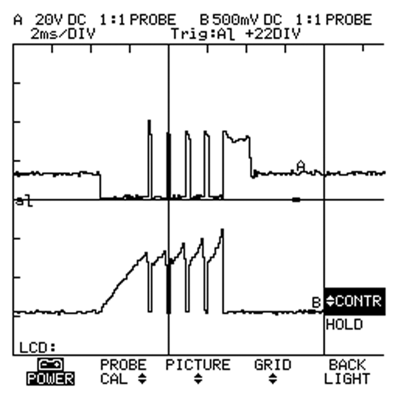
This is the MSD coil control. The top pattern is the voltage waveform. The lower waveform is the amperage draw. Each time you see the pattern rise and fall a spark is generated. This plug was fired five times at idle.
BMW has advanced to the Siemens MS43 system, which includes an ignition feature called MSD (Multiple Spark Discharge). This form of ignition control grounds and un-grounds the coil multiple times during each cylinder firing. This provides multiple flame fronts to help promote complete combustion, particularly at idle. While evaluating a scope waveform you will notice the multiple inductive kicks. If you monitor the current waveform you will see the multiple current ramps for each coil firing. The current gradually increases with each firing to a 10 amp peak. The primary resistance of a coil is about the same whether it is a MSD system or not.
The DME control unit has its own way of monitoring spark. The secondary winding (center terminal) of the coil is mounted to a 235-ohm resistor that is wired to ground. This wire is also spliced off to the DME unit. The DME monitors the voltage drop across the resistor to determine if proper spark took place. The DME is looking for two-volt spikes for each ignition spark. This spark confirmation signal plus monitoring crankshaft fluctuations helps the DME determine if misfires are occurring. The DME compares camshaft/crankshaft “sync†to identify which cylinder(s) are misfiring and set misfire codes for those cylinders. Aside from code numbers P0301 to P0312 to identify the specific cylinder, you can use a scan tool to observe the DME’s view of cylinder combustion in data. So, by monitoring the coil primary voltage and amperage waveforms, cylinder misfire codes, and scan data misfire monitor we should be able to determine which cylinder is misfiring and if the coil is at fault.
Servicing the secondary ignition system
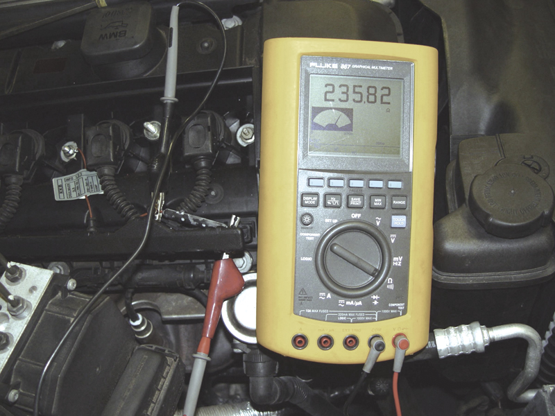
Here we are measuring the resistance of the shunt resistor. You must read 235 ohms. The red test lead is on the ground side, and the black lead on the coil side. You would need to reverse the leads to properly monitor the voltage drop as the coil fires.
Previous to the early 1990s, servicing the secondary ignition system included replacing the coil wire, spark plug wires and spark plugs. With age and heat stress they crack and leak voltage. If this is bad enough, the spark will arc to another ground path instead of that through the gap of the spark plug. Spraying a salt-water solution on the plug wires and watching them under low light may show if they need to be replaced. Otherwise, new ones should be installed every 60,000 miles. The spark plugs should also be replaced at this interval.
Proper spark plug torque is often overlooked in the process. The specification is 30 NM or 23 ft. lbs. When spark plug torque is not correct, the plug’s ability to shed heat is reduced. This and the compromised ground path reduce plug life. The effect is minimal at first, but over time will affect the plug’s performance. Throughout the ‘90s to the present BMW uses either NGK or Bosch spark plugs as Original Equipment. These evolved from a single ground electrode design to dual and four-prong electrodes in an effort to increase mileage between service intervals. It is strongly recommended that you stick with these plugs when it’s time for replacement.
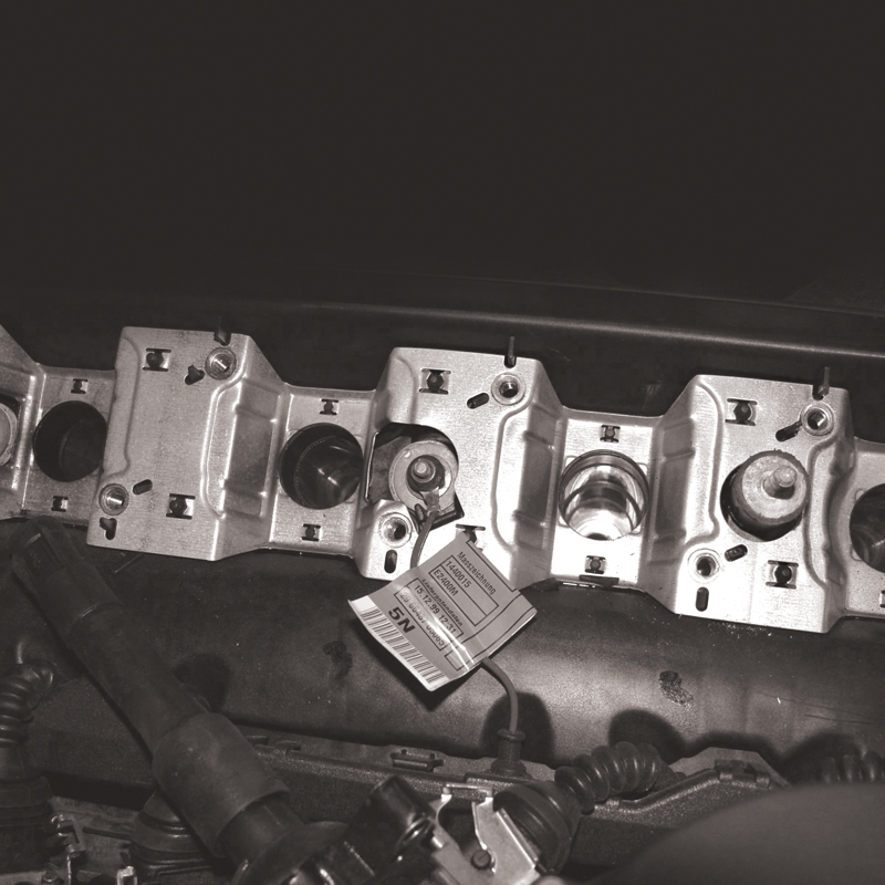
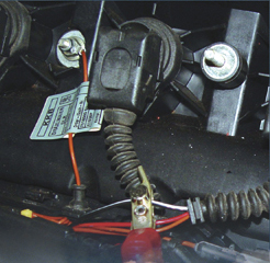
This is the ground mounting point of the shunt resistor. If this isn’t mounted properly, there’ll be no spark and the engine won’t start, so be careful when reinstalling the ignition coil.
Â
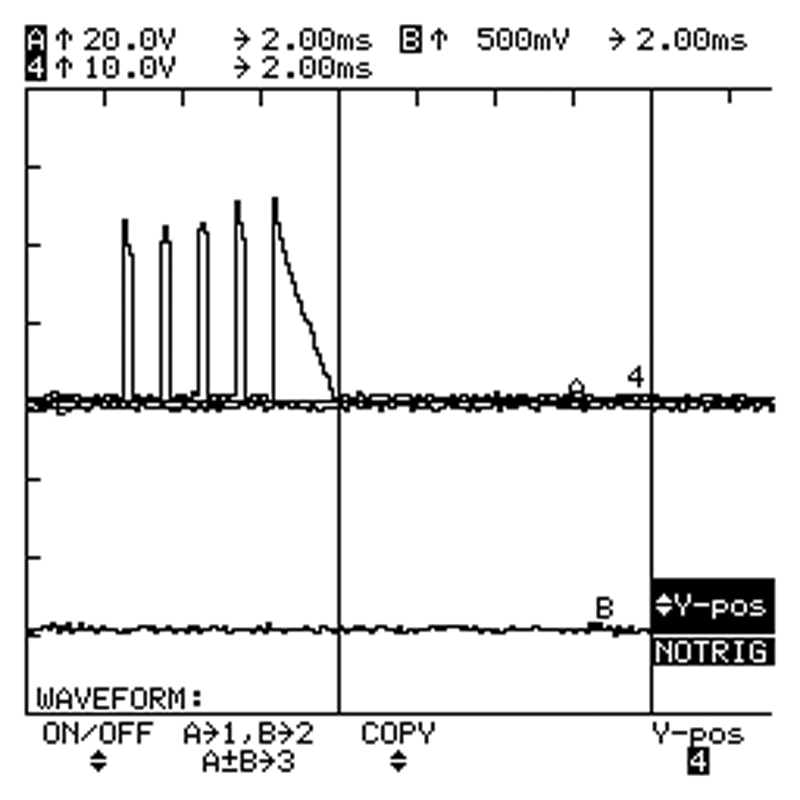
Here we are looking at the voltage kicks produced on the coil side of the shunt resistor for an MSD coil event. If these kicks are below two volts, the DME determines that there was a problem with combustion.
With the coil-over-plug design, the secondary system tune-up was reduced to changing the spark plugs. Also, with multiple electrodes, current-controlled coils and efficient combustion chambers, spark plug replacement intervals increased. Previous to ’98, the recommended spark plug replacement was at the Service Inspection II, so when the red indicator came on you installed new plugs. For post ’98 models, BMW recommends that the plugs be replaced every 100,000 miles. However, we would suggest that you allow engine performance and misfire status to supersede these intervals. Do not wait for the full 100K if there’s any problem. Poor fuel quality and neglected maintenance may influence when the plugs need to be replaced. While coils and boots carry no regular replacement interval, outside factors may cause them to deteriorate. For instance, leaking valve cover gaskets can fill spark plug holes with oil, softening the coil boots and allowing the spark to arc directly to the cylinder head.
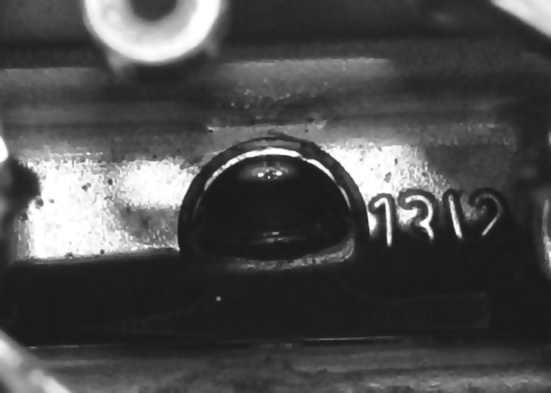
If you look down at the spark plug hole, you may see that it’s filled with oil leaking from the valve covers. This can soften the boots and possibly allow the spark to arc to the cylinder head.
Â
In closing, we should mention that ignition systems perform a stressful task. This repeated stress requires regular maintenance intervals. If these maintenance procedures are adhered to, your BMW-owner customers should enjoy trouble-free performance for years to come. If there is ever an ignition-related problem, however, you should now have the basic knowledge required to deal with it.

0 Comments