Regardless of all the advancements in climate control technology, nothing beats mother nature’s fresh air. With the added complexity of convertible tops and other body control features, however, the simple act of opening a window becomes a symphony of computer-controlled communication.
Gone are the days when push-button controls supplied power or ground to power window motors. In an effort to add features to these well-engineered vehicles, computer controls were enlisted. In any system, if a computer is in control of outputs, these outputs can be manipulated with a variety of inputs. As far back as 1990, Mercedes-Benz introduced the option of a “Comfort System,†at the heart of which was the Convenience Control Module. This module not only controlled power door locks and the sunroof, but also communicated with the Anti-Theft Alarm Control Unit. These advancements meant more features for the owner, but they also meant a greater diagnostic effort to keep these features functioning. Let’s look at the various systems Mercedes-Benz has used.
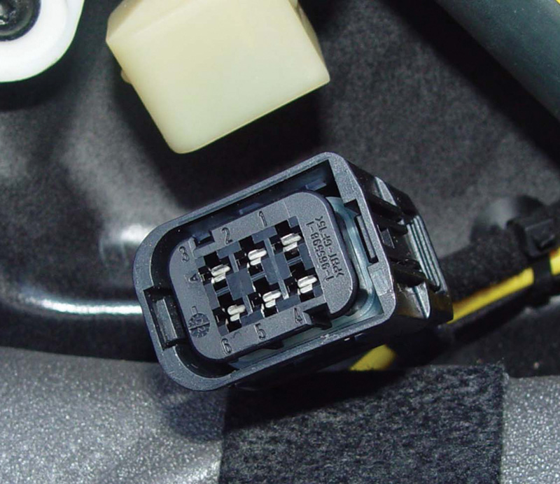
This connector is for a power window motor with a motor position sensor. In this application, pins #3 and #6 operate the window. The other pins are for the position/speed sensor. Pin #1 is the ground, pin #4 is the power supply, and pins #2 and #3 are the signal wires used for position.
Evolution vs. Revolution
Previous to 1990, Mercedes-Benz power window controls were merely switches that toggled power or ground to each motor. By switching the polarity, the motors would drive the windows either up or down. Each front power window switch had five wires: one each for power and ground, two to control the motor, and one for illumination. The rear switches had six wires, the additional one coming from the front driver’s switch to control the motors.
As mentioned earlier, the computer-control revolution began in 1990. The 124 and 129 chassis were the first vehicles to have the power windows controlled by an electronic unit. The 124 chassis power window circuit is controlled by a Convenience Control Unit, as we said, and the 129 chassis is slightly different in that it is a convertible. With convertibles, the power windows are controlled by a Power Soft Top control module. The reason for this is the power windows have to work in concert with the convertible top. When the driver commands the convertible top to open, each window is opened to provide clearance so the window doesn’t rub against the door seals.
The front power window switches on these computer-controlled systems still have five wires, but a few of them now serve a different purpose. We still have one wire providing power to illuminate the switch. We also have one wire devoted to ground. The other three wires come directly from the Convenience Control Unit, not the power window motors. These wires have signal voltages on them. By toggling the switch up or down, one of these three wires would be connected to the ground wire effectively grounding this signal. When the Convenience Control Unit receives this ground signal, it provides the proper polarity to the window motor to drive the motor up or down, depending on which signal was brought to ground. We have three signal wires, one is to command the motor up and the other is to command the motor down, so what’s the third one for?
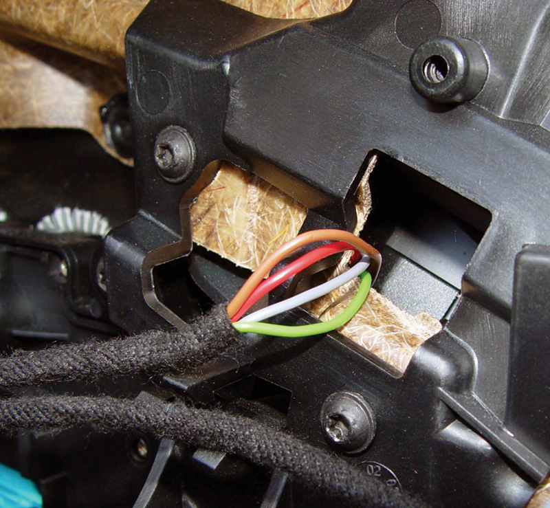
Here we have the result of “resistive multiplexing.†Four wires control the front power windows on a two-door convertible. The brown wire is ground, and the grey and green wires carry the signals that command the motors, grey for the driver’s side and green for the passenger’s side.
Value-Added Features
Mercedes-Benz added a new feature. Switching this third wire to ground signals the control unit to command the window motor all the way open. The driver no longer has to hold down the button to pay a toll. This “Auto Down†feature allowed the driver to get back to driving. Keep in mind that the 126 and 201 chassis never got the “Comfort System,†having instead conventional power window wiring.
Starting in 1992, Mercedes-Benz introduced the 140 chassis. This being the company’s luxury flagship, it included more control of the power window circuit. The motors included a four-wire position/speed sensor. This sensor determines when the window is reaching its travel limit, and stops the motor (more on this later). In ’94, the entire Mercedes-Benz line-up (except convertibles) utilized the Comfort System and the Convenience Control Unit to control the sun/moon roof as well as the power windows. Another interesting feature is the pair of signal wires from the PSE control unit to the Convenience Module. In the lock mode, if the key is held in that position the PSE module will signal the Convenience Module to close any open windows. Knowing how these features work will help in diagnosis of a problem with window operation.
At the same time that computer-controlled features reduced the amount of wiring in a vehicle, paradoxically it also increased the amount of wiring in a vehicle by adding more control units. A greater effort was required to reduce wiring complexity. Let’s see how Mercedes-Benz chose to achieve that.
New Layout
With the introduction of the 170 (SLK) and 208 (CLK) chassis, a new power window switch was added. In fact, a whole new layout was launched. Too many body control features are present for one Convenience Control Unit to handle. Mercedes-Benz chose to distribute more control units throughout the vehicle. Instead of the Comfort System using the Convenience Control Unit as a single central control, the Comfort System features were distributed to several components such as the Door Control Modules. These modules control the power window motor, mirror heating and mirror retract functions. More features would be added later. It would also relay memory function requests to other control units such as those for the telescopic steering wheel and power seat module. Since the power seat and memory switches are mounted in the driver’s side door, all of the wiring is directed to the driver’s side door module. This relays the seat commands through the CAN bus to the power seat control unit, which eliminates the need to run wiring outside of the door directly to the seat module, thus helping to reduce wiring.
In an additional effort to reduce wiring, the power window switch no longer has five wires attached to it, but only three. One wire is still used for illumination. That leaves two wires to inform the door control module to open the window, close the window, or open the window all the way. This is achieved with “resistive multiplexing.†Multiplexing is the process of using multiple signals on a single wire. Resistive multiplexing is all about changing the signal voltage by changing the resistance applied for each switch position. In other words, with the switch in one position, the first wire carries reference voltage, which is sent through a resistor to the second wire that is grounded, generating a specific signal voltage. By putting the switch in a different position, a different resistor changes the reference voltage to a different signal voltage. When the control unit sees these different voltages it is programmed to respond with a different output for each voltage input. This is how we can have three different signals on one wire, therefore reducing the number of wires in the vehicle.
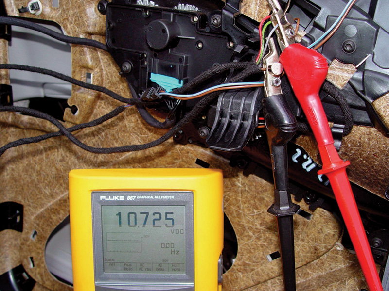
In this test of the reference voltage from the door control module, we see approximately 10 volts. Pushing the button for the driver’s side power window should make this voltage reading change.
Power Window Diagnostics
With power window systems previous to 1990, testing is straightforward. You could remove the door panel and check for power and ground to the motor, but that would involve additional labor that we have not yet justified. Also, banging on the inner door panel to see if you can loosen up a stuck armature is at best inconclusive. We would suggest you start by checking fuses. This requires the least amount of labor. However, you may still have to diagnose why the fuse blew.
We would suggest you continue testing at the power window switch. It is easier to get to and you can perform many more electrical tests without removing the door panel. By removing the ashtray and storage tray (if applicable), you can remove the shifter cover and expose the window switch wiring. From here, you can determine if the switches have the power supply and ground they need. We can also test the switch contacts providing power and ground to the motor. Additionally, we can bypass the switch contacts with jumper wires and verify that correcting a power or ground problem will operate the motor. If we verify power and ground to a motor and it still does not work, we can now justify removing the door panel for further testing.
If you have a power window problem with the Comfort System, there are three steps you can take to isolate the cause. Step one is to perform functional testing of other related components. If the driver’s side window motor is not working with the manual push button, you may want to see if you can command the motor open or closed using the Comfort System. By turning the key in the door lock, or holding the remote button down, you can command the windows closed (and open in some models). If the window functions at this point, you know that the window motor and a portion of the Convenience or Door Control Module are working fine. If the window does not function, you may want to focus your testing on the door control unit and the window motor.
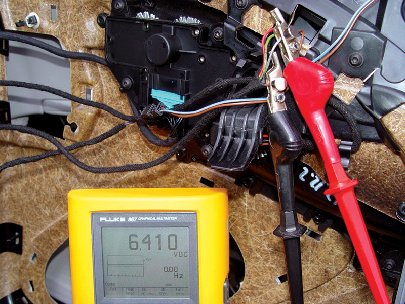
This is the result of pushing the power window button in the up position. The voltage on the signal wire has indeed changed. When the door control unit sees this specific voltage, it will command the motor up.
Another weapon we have in our troubleshooting arsenal is Star Diagnosis. The ability to use a scan tool to monitor inputs and bi-directionally control outputs is a tremendous advantage over basic electrical testing. Of course, scanning for any trouble codes may give an indication of where to begin your testing regimen.
If you monitor the power window switch inputs, you can see if the door control module recognizes the signal change. If you see the change, you can move on to the output of the window motor. If you do not see the switch input change, you now know the problem is in the switch. At this point, you need to verify if the switch is malfunctioning or if there is a wiring problem.
Don’t forget that there is more involved in the power window motor of the 140 and 220 chassis. These motors have a position/speed sensor built into them. If the symptom is erratic position of the window, you may have a bad position/speed sensor. This is a four-wire sensor, one wire is the 12V power supply, one is ground, and the last two carry the signals back to the control unit. If you scope these wires, you will see that they carry 5V square wave signals. The signals are out of phase by 50%, so you will observe them alternating back and forth. The control unit memorizes the square wave position and counts the square waves to know in which direction the motor is moving and how far it’s gone. It also counts pulses to check the speed of the glass to detect blockage in the up direction.
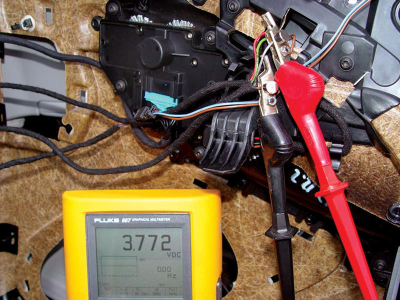
Here we have the result of moving the switch in the down position. Notice how on the same wire we have a different voltage. When the door module sees this voltage reading it commands the
motor down.
As well as verifying that you have a power and ground command to the power window motor, you may have to verify that the position/speed signals are indicating motor position to the control unit. This would be your third step in the diagnostic process, verifying your scan tool findings with electrical testing. This may involve some additional labor to remove panels and get access, but you should be able to give an estimate on the time involved and get it approved. Functional testing, scan tool diagnostics and electrical testing will ensure that your diagnosis is accurate and timely. Now We Actually Have To Fix It
Once you have determined what the problem is, you now have to fix it. If you isolated the problem to a control unit, you simply have to replace it. Very often when replacing a control unit, you have to version code it. Different options may have been installed on this vehicle and to make sure these features work, the new control unit has to be “personalized†to this particular vehicle. This process is known as version coding. Most often, the Star Diagnosis scan tool will download the programming that is already in the old control unit. After the new unit is replaced, the scan tool will then upload the program to it. Now, the new unit will have the same programming function as the old unit. If the problem is in the switch, then simply replacing the switch is all you have to do. In some older models, coding can be done manually.
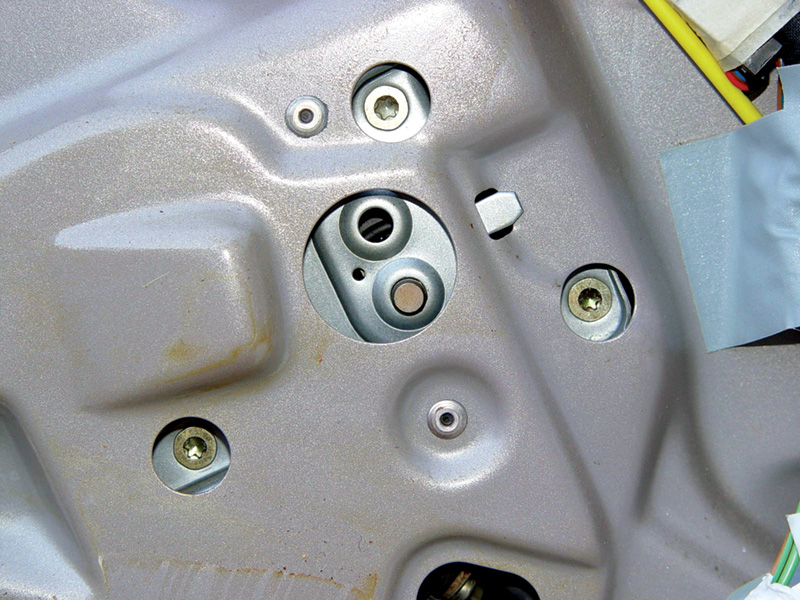
These are the mounting points for the motor. Removing the three Torx screws will release the motor. But if the new part is an assembly, you will have to drill out the rivets that mount the regulator to the door frame. Rivets give more clearance than a nut and bolt, so stick with rivets.ÂÂ
Replacing the power window motor is a little more involved. First, you have to remove the door panel. This is a cosmetic piece, so you want to know exactly how it is to be removed so it’s not damaged. Also, since it is a cosmetic piece, many of the mounting bolts and nuts are hidden behind plastic covers. Take the time to evaluate your service information and you will save time and money. Almost every door panel Mercedes-Benz produces uses mounting bolts and clips to hold it on. Some other models use guides that slide into channels in the door frame, so sometimes they have to be maneuvered in a particular direction for removal. Once the panel is off, you have to contend with the sound-proofing material. This can be a plastic sheet, or a foam insert glued to the door frame. Care should be taken during its removal so it can be reinstalled properly during reassembly. At this point you will need to know how the power window motor is serviced.
On some models, the motor is replaced. On other models, the motor and regulator assembly are replaced as one unit. Check your service information. Sometimes the window needs to be in a particular position in order to be removed. This may be a problem if the motor is malfunctioning and is not stopped in that position. You may have to disassemble the assembly inside the door and/or drill out additional access holes to remove a stuck motor.
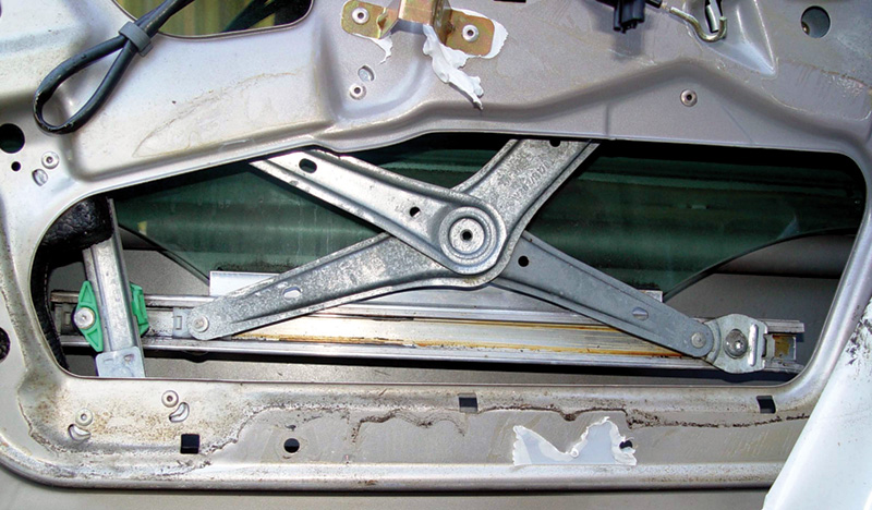
Here is the regulator assembly in the door. The channel going across the bottom of the scissors arms needs to be lubricated as these parts slide in the channel. If you have to replace the regulator assembly, you must separate the glass from the channel and support the glass. You will also have to drill out the rivets that secure the assembly.
Upon reassembly, lubricate sliding components with light grease to reduce the chances of the regulator binding. Any friction in the regulator will increase the load handled by the window motor. This can cause premature failure, or it can cause the “excessive force limiter†to kick in and stop window operation. Also, these regulator units are sometimes mounted with rivets instead of bolts in low clearance applications. The rivets have to be drilled out and the proper size rivet has to be used to reattach the assembly so nothing comes in contact as the window is being operated.
Final Touches
Mercedes-Benz recommends that we disconnect the battery when the power window is serviced. This action, or replacing the control unit, will put the windows out of “sync†with the control unit. If the power windows are not synchronized, then the automatic features will not work. On most models, to synchronize the windows with the control unit manually, push the up button only to the first detent until the windows are closed and hold the switch for two to four seconds. This will need to be done for each control unit/window combination, and on some models the doors must be closed for it to work. Now, each control unit knows the motors are at their upper limit and can start using the position/speed sensor to operate the automatic features. This procedure is not required on the new S-Class and CL.
“I Need To Check The Oil In Your Power Windowsâ€
We would be remiss if we did not inform you of a special protection option that is NOT available in the U.S.: hydraulically-operated windows! The door control module operates a valve block that uses hydraulic fluid pressure, provided by a pump, to open and close the power windows. This is a special option that most of us will never see, but we felt it was our responsibility to inform you that this technology exists.
Â
Â
Â
Â




0 Comments