Summer is almost upon us, and with the warmer weather come customers hot under the collar about air conditioning performance.
Advancements in technology are everywhere. From computer-controlled systems to new materials, the automotive industry is marching forward to provide lower emissions, increased safety and more creature comforts. The creature comfort in question here is Automatic Air Conditioning (AAC), which provides more efficient cooling of the cabin. Driver, passenger, and even rear passengers (Thermotronic) can each enjoy their own personal space, at least when it comes to temperature regulation.
As a technician you may feel these advancements come at the price of added complexity in diagnosis and difficulty of service, but this is not entirely true. Yes, the systems are more complicated, but the basic principles of air conditioning still apply. All you need to know is how the advancements improve system operation and take them into account, particularly during troubleshooting.
Basics
In order to understand the changes in air conditioning systems over the past few years we first need to have an understanding of the most basic principles. We will start with what is considered the heart of the air conditioning system, the A/C compressor. Its function is to take the mechanical energy of a running engine and convert it into a pumping action that moves refrigerant throughout a closed system. It takes in a low pressure gas and pressurizes it into a high pressure gas. During this process, due to the compression of the gas and the friction created, the temperature of the refrigerant is increased as well.
This hot pressurized gas is sent to another component called the condenser. The function of the condenser is just that. It functions like a radiator — air flows over its fins and tubes cooling the contents. As the refrigerant cools it condenses into a high pressure liquid and exits the condenser. The refrigerant then passes through what is called a receiver/dryer. This component filters out impurities in the refrigerant charge, both chemical and physical debris.
The next component this high pressure liquid passes through is, in the case of Mercedes-Benz vehicles, an expansion valve. Its job is to meter the liquid through an orifice, forming a low-pressure liquid. This low-pressure liquid now enters the evaporator core. This is where refrigeration actually takes place. As the low pressure liquid passes through the evaporator core it changes state and absorbs the heat in the air around it.
A blower motor forces either fresh air from outside the car, or recirculated air within the cabin, through the evaporator core and the core absorbs the heat in the air. It’s sort of like a radiator, but it works backwards. Instead of the heat of a liquid being dissipated into the airstream, it’s the other way around. As the low-pressure liquid absorbs the heat of the cabin it evaporates and becomes a low-pressure gas. This passes back through the expansion valve, giving the expansion valve an indication as to how much heat is being absorbed (load) and opens and closes the valve accordingly. Finally, the low-pressure gas is returned to the compressor and the process begins all over again.
Automatic Air Conditioning (AAC)
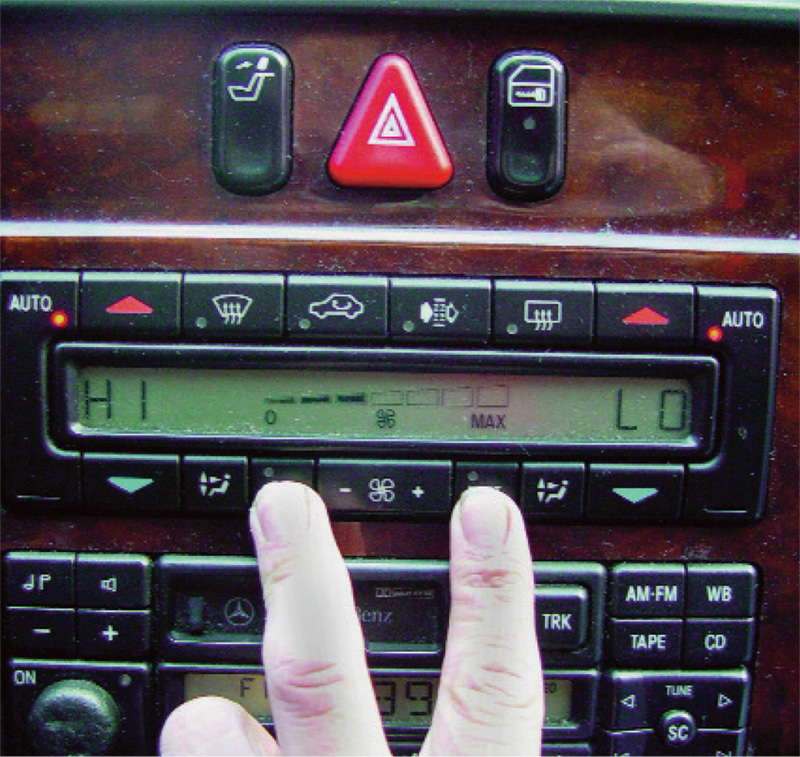
By positioning the driver’s side temp to high, the passenger side to low and pressing the “ECON†and “REST†buttons, you can have this AAC control unit display codes. You can also command output control and read sensor values.
The purpose of AAC is to control temperature and direction of airflow according to the occupants’ desires. This is accomplished by using computer controls to monitor cabin conditions and outside temperatures, and to provide the changes required to respond to occupant requests. Let’s look at the typical players involved in this symphony of climate control. The first component we will discuss is the climate control computer. This is the brain of the system, both monitoring input and manipulating outputs to respond to the passengers’ needs. The control unit can be on its own, or, in the case of most Mercedes-Benz vehicles, can be incorporated into the control panel in the vehicle. Self-diagnostic functions have also been incorporated in their design.
Next on our list are the environmental sensors. These relay information back to the computer. They indicate air temperature outside the vehicle, inside the vehicle (in the case of dual zone climate control, the temperature in both the driver’s side and passenger’s side ducts). Mercedes-Benz has also incorporated a sun load sensor that monitors ambient sunlight and adjusts air conditioning controls to compensate for it. More input sensors are used to control both the A/C system and heating systems. A/C refrigerant switches/sensors are used to monitor refrigerant pressure and temperature to control compressor operation, hence temperature. Aside from reading refrigerant temperature and pressure in the lines, there are also sensors that read the temperature of the evaporator. This tells the control unit when the evaporator core is starting to freeze so the AAC unit can prevent ice from forming and blocking air flow. Additional sensors include a Multifunction sensor that passes on humidity information to the AAC unit.
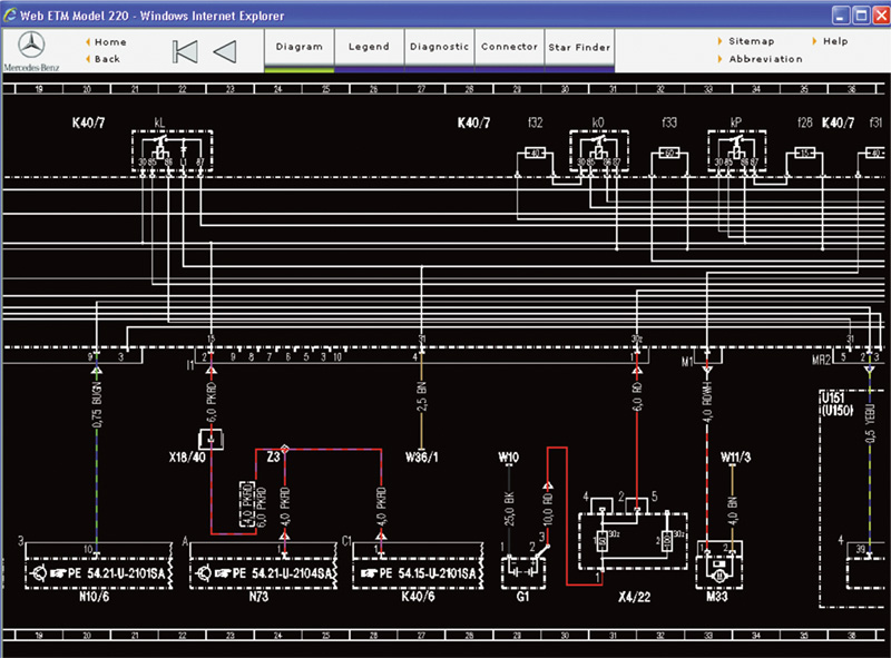
With a paid subscription to www.startekinfo.com you have access to factory wiring diagrams. In this diagram for the S-Class (220 chassis), look at the wiring for the left SAM. If you follow the wire from component N10/6, you’ll see that it controls the A/C Compressor Control valve.
On the output side of the equation is the compressor clutch (not every vehicle has one), solenoids and mode door motors. These outputs control when the compressor cycles on and off, how much heated coolant will be allowed into the heater core and what vents the airflow will be directed out of. As mentioned earlier, the more temperature controlled zones in the vehicle’s interior the more sensors and motors will be added, but their basic operation will be the same. Up until recently most of these “mode door†controlled outputs were handled with a system that used engine vacuum and redirected it to various diaphragms under the dash, attached to the HVAC control assembly, to change airflow direction. These systems have since been replaced with electric motors that control mode door operation. In the past a mechanical lever positioned a door that controlled the temperature by mixing the cool air of the A/C system with the heated air of the heater core. With ACC, the control unit operates an electric motor blend door (or two, or more) in response to changes in sunlight, ambient temperature and occupant requests. These motors also provide feedback as to their position for diagnostic purposes. When replacing these motors or the AAC control unit you will need a factory scan tool, or equivalent, to calibrate the motor positions.
PSI
One of the most basic tests you can perform on the hardware of the A/C system is monitoring the high and low side pressures. As we discussed earlier, the refrigerant system is broken down into four phases: high pressure gas, high pressure liquid, low pressure liquid and low pressure gas. Monitoring these pressures will indicate if there is a problem in the system and where the problem may be. Typically, Schrader valves are conveniently mounted in the air conditioning lines on the high- and low-pressure sides of the system. They allow you to monitor the gas pressure in the system while it is operating. By monitoring both sides of the system you can usually get a good idea of what the performance problem may be. We have all been taught that with a proper refrigerant charge the low side of the system can be pulled down to 20 to 30psi. The high side pressure will increase more depending on ambient temperature and can run anywhere from 125 to 350psi. These pressures show the compressor is capable of creating suction on the low side and generating high pressure on the high side.
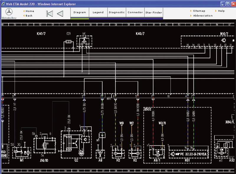
When looking for the compressor in a wiring diagram from the www.startekinfo.com website, you need to know that it will be found in section 54 Electrical Systems – Equipment and Instruments. In the case of this 220 chassis, the left Signal Acquisition Module controls the A/C compressor. Trace the wiring for component A9.
What do we do when the A/C system performance is not up to snuff? We check these pressures. If the pressure of the high side gas is too high we suspect a restriction in the system. On the high side, this can either be a clogged receiver/dryer, or a stuck-closed expansion valve. If the high side pressure is too low, then most likely the expansion valve is stuck in the open position. There are diagnostic flow charts provided by Mercedes-Benz that outline the testing of basic pressures and the problems associated with various readings. These pressure charts have been used for years on basic A/C systems.
In the mid-’90s Mercedes-Benz started to use variable-displacement compressors. These use a moveable swash plate that can change the piston stroke travel. Thus, in high load conditions the displacement of the compressor can be increased and for low load situations it can be decreased. This allows greater control of compressor load as the engine rpm changes in response to the driver’s demands. As a result of this design change, you need to know the position of the swash plate if you are going to use pressures to determine what is wrong with the system. In addition to knowing the high and low side pressures, you will need to know the command from the AAC control unit for the swash plate position. There is no feedback on swash plate position, so you will just have to monitor the pressure change relative to the command change by increasing A/C request through the control panel (lowering requested A/C temperatures). A solenoid, called the A/C Compressor Control Valve, indirectly controls the position of the swash plate. Let’s see how this is done.
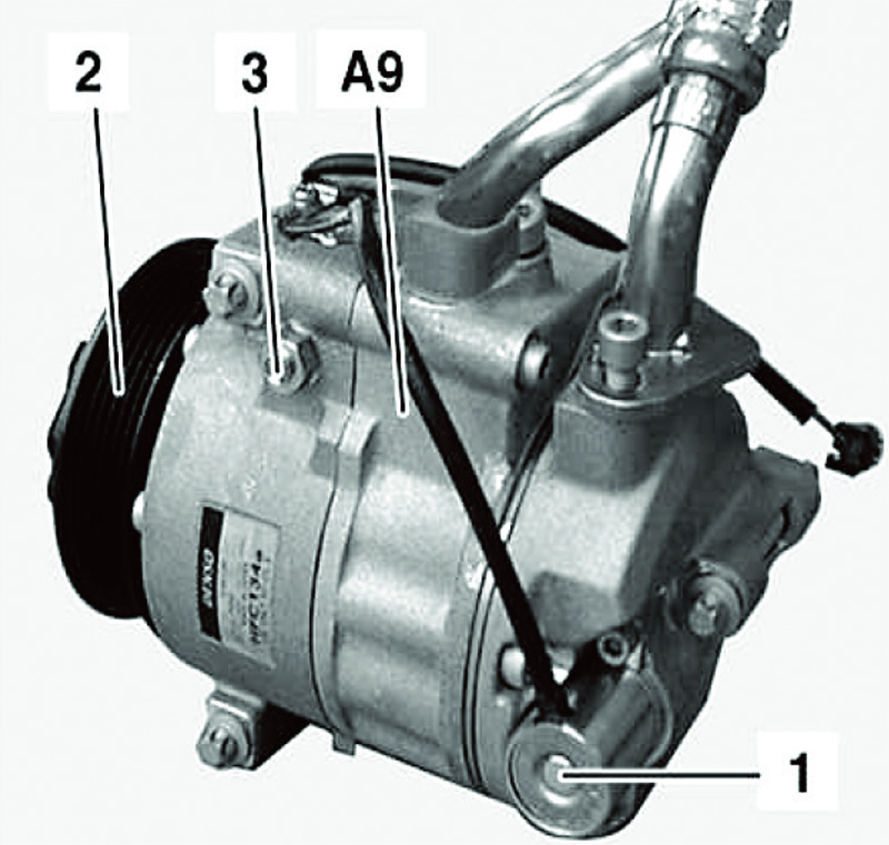
The A/C Compressor Control valve is pictured here as component #1. This valve controls the pressure applied to the case of the A/C compressor. On vehicles without an A/C clutch, this is how the compressor is turned on and off.
The A/C Compressor Control valve has a pre-pressurized diaphragm mounted inside the valve at just below 30psi. This valve is connected to the intake, or low pressure side of the compressor. If the low side falls below diaphragm pressure, the A/C Compressor Control valve is commanded for a low opening and can be as low as 2% (A/C off position). You can monitor this manually with a DMM, or through your scan tool. This valve position allows high side pressure into the compressor case. The pressure pushes the swash plate in, thereby reducing piston stroke and A/C compressor output. This is also how the compressor is shut off. With the control valve at 2%, it is wide open and the high pressure reduces the piston stroke to nil, eliminating compressor output but still keeping the internals lubricated. If the low side pressure goes above that of the diaphragm, the A/C Compressor Control valve is opened up to 100%. This allows the swash plate to move to a position increasing piston stroke and overall pressure in the high side of the system. So, basically low side pressure and the A/C Compressor Control valve control the pressure in the case and the position of the swash plate, and ultimately the output of the compressor.
Some compressors still use a compressor clutch. The clutch is mounted behind the pulley. This is still necessary to engage and disengage the compressor and is still a potential fault, but conventional diagnostics prevail here. Check the amp draw of the clutch, and listen for noisy compressor engagement. There is a TSB # P-B-83.55/87 that informs us how to bypass the compressor with a smaller serpentine belt. If the noise goes away there is a problem with the A/C pulley bearing. You can replace the front clutch and bearing assembly in the vehicle, so you do not have to remove the compressor. That’s a relief since this compressor is one of the harder ones to R&R. A/C compressors that do not use a compressor clutch use a rubber coupling.
Self-Diagnostics?
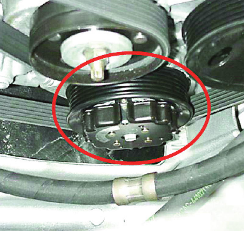
On vehicles with this compressor pulley, you will definitely have an A/C Compressor Control valve to turn the compressor on and off. If the compressor seizes, the outer pulley separates from the inner pulley, thus saving the belt.
Not only has Mercedes-Benz incorporated a self-diagnostic function into its AAC systems, but you do not need a scan tool to access them. The control panel of the AAC system is the technician interface. This rule applies from the early ‘90s into the late ‘90s. Otherwise, Star Diagnosis, or its equivalent will be required. If you are between these years, the process is simple. On single climate zone systems with the ignition key on, you set the temperature to “LO†and within 20 seconds apply the “REST†and defrost buttons at the same time. The LED in the recirculation button will flash and the liquid crystal display should show “diAâ€. Now press the “AUTO†button and a code will be displayed if one has been set. Push the “AUTO†button again and you will advance to the next code. Apply the “AUTO†button again until the codes start to repeat. To clear the codes, use the temperature arrow up and arrow down button simultaneously and hold them down for more than five seconds. In the event that you do not want to erase the codes, you can apply the “AUTO†button and the faults will not be cleared. Shutting the key off will end self-diagnostics.
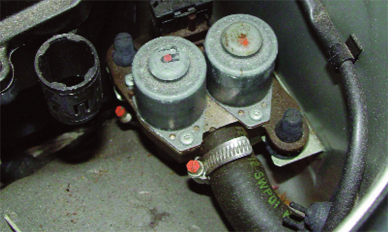
Here is a Duo-Valve assembly for dual zone climate control systems. This valve is normally open (defaults to full heat if there is a failure) and the AAC control unit grounds it to close it during A/C operation. Make sure these valves are closing when A/C is requested.
On dual zone systems, it is slightly different. With the key on make sure the driver’s side temperature is set to “HI†and the passenger side is set to “LOâ€. Within 20 seconds press the “REST†and “EC†buttons together and hold them down for over five seconds. The display will indicate “di Râ€, the LED in the recirculation button will blink and once again pressing the “AUTO†button on the passenger side will advance you through any stored trouble codes. The letter “E†is displayed on the left side of the LCD and the code on the right. Hitting the “AUTO†and the arrow button to increase fan speed for two seconds will clear the codes and “FF†will be displayed on the screen. Pressing the “AUTO†button at this point also cancels the code clear. Shutting the ignition switch off ends the process.
Self diagnostics are always available to the Star Diagnosis unit, or its aftermarket equivalent. With Star Diagnosis, not only will you be able to pull and clear codes, but you will also be able to activate output controls such as the A/C compressor clutch, mode door control, and monitor signal voltages in the data stream. This information can save hours of diagnostic time on dual and multiple zone systems like Thermotronic. An excellent way to take advantage of the data-stream is to monitor temperature sensor inputs and opening percentages of mode door outputs. Mode doors move from 0% to 100%. This should indicate to you if a motor is binding or stuck. The temperature sensors should change their signal voltage when different temperatures are selected and the system is working properly.
Outside The Box
One quick note as we close: Not all low A/C outputs are caused by the refrigerant system. Mercedes-Benz uses electric heater control valves to supply hot coolant to its heater cores. These valves de-energized are open. This way if there is a failure in the system, you will still have full heat. If these valves do not close when commanded, they still allow hot coolant into the core. This can increase the temperature in the cabin to a noticeable degree. Always make sure the heater control valves are closing properly when the A/C isn’t as cold as your customers would like it to be.Â


0 Comments