
When we think of collision repair, we normally think of metal work. That is, body reconstruction that consists of cutting, straightening, welding, assembly and finishing. Metal panels are repaired/replaced till the vehicle looks the same as it did originally, and has the same structural integrity it had before the accident. It is sometimes described as something between rebuilding a puzzle of metal pieces and artistry.
When we think of electrical systems, we think about power being properly supplied from the battery to the various components of the vehicle. We think about switches, relays, control units, sensors, solenoids, and all the power and ground wiring in between. We don’t necessarily think about any relationship between electrical systems and body work, especially where the ground side of a circuit is concerned. But any good collision repair technician should check the power supply, the electrical components themselves and the ground connection to make sure everything works the way it did before the mishap.
The Definition of a circuit
In order to understand ground paths, you first need to know the definition of an electrical circuit. In the automotive industry, a battery is an electrical storage device that chemically stores a difference in voltage potential. Between the positive and negative terminals, this is about 12.6 volts, depending the temperature. The voltage that leaves the positive terminal wants to return to the negative terminal the fastest way it can. The same can be said of an alternator’s output if the engine is running.
In any event, an electrical circuit is voltage and current leaving one battery terminal, passing through wiring to an electrical component performing some sort of work (for example, a light bulb or a solenoid), and then returning to the other terminal via more wiring and/or sheet metal. Power source, electrical component and ground path is all you need to know.
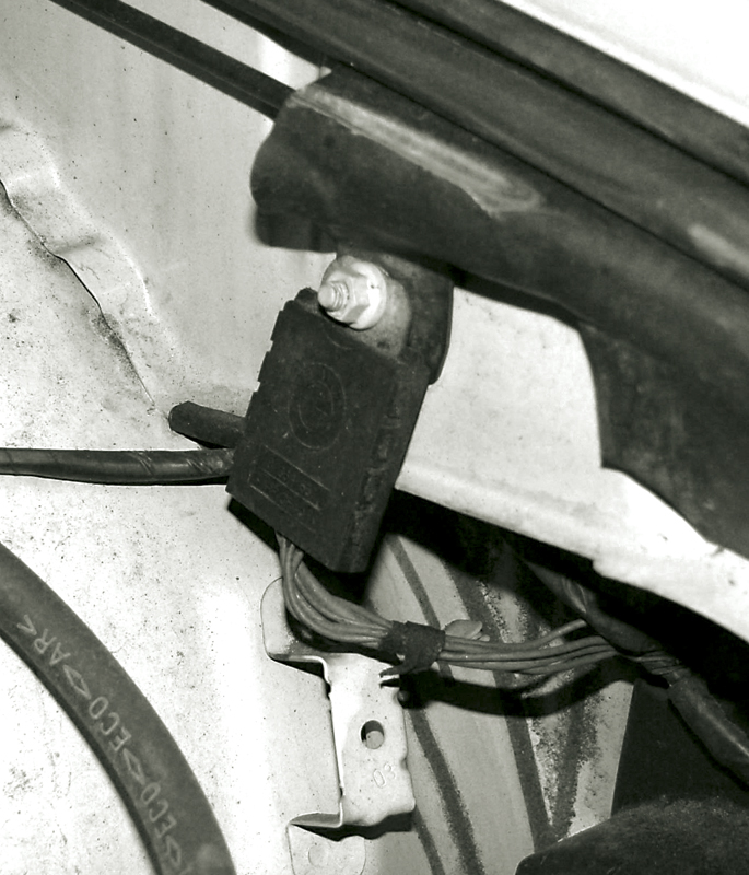
This is not an electrical device, but a multiple ground point. All those brown wires are connected together on a buss bar inside the black plastic cover. This is bolted to the inner fender and forms the ground path for multiple items.
Power distribution wiring starts at the positive terminal of the battery. It then travels directly to components that can be switched on or off with the ignition key in the off position. It also makes its way to the various control modules to supply keep-alive memory power. Finally, it supplies the ignition switch, which also continues the power distribution path around the vehicle for components that run while the ignition key is on. Once electrical power is supplied to all of the various consumers through their circuits they need to find a way back to the power source be it either the battery or the alternator. This is done through the ground path. You’ll often find ground wires on components, but these are only part of the path.
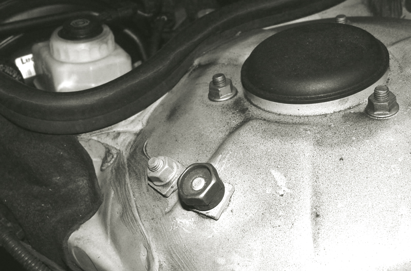
This ground stud is provided by BMW for use in the event of a dead or weak battery that cannot start the vehicle. The “jumper†cable ground wire is attached to this stud and forms the ground path for the boost. If this fender is not properly grounded, the jump won’t work.
When dealing with electrical systems, we do not necessarily think that there is much past the ground wire at the grounding point. If you have ever run into open circuit problems you know this is not true. The ground wire is only one part of the ground circuit. The rest is the body of the vehicle itself. Many years ago, manufacturers realized that instead of having extensive ground wiring returning to the power source, they could reduce wiring complexity and weight by using the body of the vehicle as a common ground. The body/chassis of the vehicle carries the electric current back to the ground cable that is connected to the negative post of the battery.
So what?
When dealing with the ground side of any electrical or electronic device, you can’t just think about the wire the ground wire leaving it. You also must think about the body of the vehicle itself. Ground paths may have been damaged by the accident, or during the course of collision repair. Metal may have been crushed and/or ripped away from the main structure. When attaching replacement inner fenders or inner body panels to the main structure or frame, you need to insure that there is a proper ground path with minimal resistance in the “circuit†that is formed by the metal body panels. How these metal panels connect to one another is critical in maintaining an electrical ground path.
The following information on proper body repair techniques and how to test and verify that the ground path is sufficient to handle the load of the electrical components in the area will help you avoid problems that may be difficult to diagnose.
After the storm
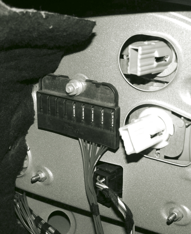
This ground for the rear lighting is mounted to the trunk support frame. These are often steel panels that are spot welded to the rest of the body. Since the metals are the same, the weld forms the ground path.
After accident damage has taken place and an estimator has done the assessment, you now have the opportunity to find out what really has to be done to repair the vehicle. During the disassembly phase, pay close attention to wiring while removing lighting components and other electrical connections. We realize you do this anyway, but for the purpose of this article we would like you to pay particular attention to the ground wires. All of the grounds must be put back in the same location. Don’t focus only on the ground point, but also on the panel it is being mounted to. In the event that a panel needs to be replaced, you need to remember how they are going to be attached. With typical steel panels, this is usually not a problem. Add another metal to the equation, however, and things get complicated.
When typical mildÂÂ steel receives damage, you typically work out the dent. If the damage is severe enough, you may cut away a damaged section and weld in a new piece. The metal is strong and the weld is strong. Both conduct electricity well, so we can pretty much insure that there will be no ground problems, even when dealing with the new harder steels. In all-aluminum repair, welding is usually not recommended. While the weld may be strong enough, the metal just outside the weld has been weakened by the heat of the process. Epoxies, resins, adhesives and/or mechanical binding, such as rivets, are commonly used. The mechanical connection between panels can provide a sufficient ground path.
So, when do we have to worry about a ground problem? The answer is when dissimilar metals are involved. Starting in 2000, BMW has used aluminum not only for body panels, but also for structural members, both in the sub-frame and the body. Take the 2004 5-Series, for example. It boasts an aluminum front end, from the firewall forward. The rest of the body is a conventional steel alloy. In frontal collisions involving significant damage, the front end is neither to be pulled straight, nor are individual sections to be replaced. To maintain the original structural integrity, the entire front end must be replaced. Special jigs are recommended for this extensive procedure to align the sub-structures, but there is still the question of how we are going to join these two different metals.
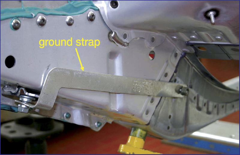
On certain vehicles where the front end is aluminum and the rest of the body is steel, ground straps like these are necessary to ground the two parts. There is no weld to form the ground path, and the structures are bonded with adhesives and rivets (courtesy Collision Industry Conference).
Adhesives and rivets are the methods of choice in connecting these dissimilar metals. The adhesives are proprietary and only those approved by BMW may be used. Also, the rivets for these applications are only available through your BMW dealer. Another proprietary component that helps the ground situation is the Electro Magnetic Conductivity (EMC) screw. These are also only available through BMW, and are required to insure a good ground path when securing the body panels together.
During disassembly, you will notice another important part of the ground path called the ground strap. This metal band bolts to the aluminum front structure and the steel frame of the vehicle, thus connecting them electrically. These straps are critical to providing a robust ground path for all the many electrical items mounted in the front of the vehicle. Once these straps have been refitted on clean metal surfaces, you can test the ground path from the front of the vehicle to the rear where the battery is often located. What’s a simple way to test for proper grounding to insure we have done the job correctly?
Voltage drop
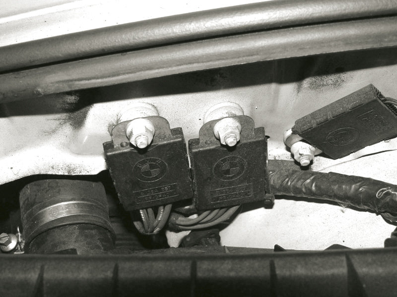
Here we have multiple ground connections attached to an inner fender support. As the fender is asked to ground numerous electrical components, you need to insure the fender is properly grounded to the rest of the body in order to handle the load.
While the body is apart may not seem like the right time to start checking grounds, but it makes sense to do it at a time when you can fix the situation if there is a problem. It’s actually quite simple. Of course, first make sure it’s safe to install the vehicle’s battery and connect the ground cable. Now connect a jumper wire of sufficient gauge to the hot terminal of an electrical consumer in the area of the vehicle where the repair is being made, and the other end to the positive terminal of the battery. The consumer should be a fairly heavy load, such as a headlight bulb or a cooling fan motor. The headlight should light, or the cooling fan should spin (be careful). While the light is lit, or the fan motor is running, measure the voltage between the ground side of the bulb or motor and the negative battery post (be sure to connect the black wire of your voltmeter directly to the negative battery post — this is absolute ground and the reference for any voltage measurement).
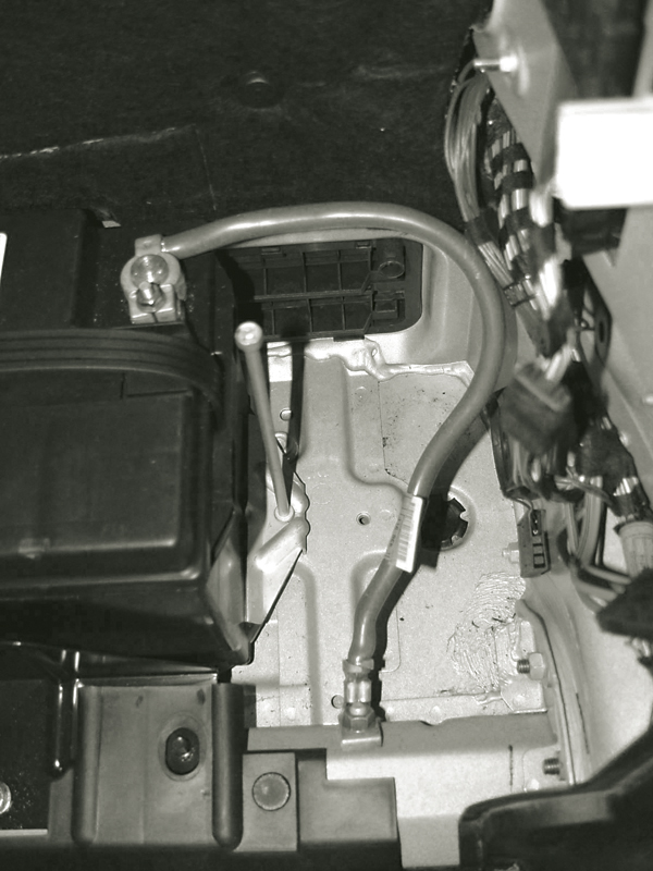
Notice how the battery ground cable is bolted directly to the frame. This is important since another ground cable is mounted between the engine and the frame at the front of the vehicle. This forms the ground path for the starter. Remember, when doing voltage drop testing always connect your ground test lead directly to the negative battery post only!
If the body of the vehicle is acting as a good ground, the voltage measured will be minimal. If the ground is poor, then you will measure some voltage. For instance, say a headlight is dim and the reading is about 2.5V. This means that only about 10 volts is making it through the light, indicating a poor ground that needs to be repaired — you’ll know the resistance is on the ground side because you’ve used a jumper for hot. As the vehicle gets put back together and more electrical components become functional, this inadequate ground will be loaded even further, probably to the point that the electrical components will not work. Double check the ground straps, welding and riveting to improve the ground path. Although it should be obvious, we should mention that there must be no coating or material between a grounding strap or bolt and its mounting point.
What to watch for
The customer is already feeling the stress of an accident and the hardship of being without the vehicle. Don’t add to this by returning it with malfunctions. Avoid comebacks by testing and verifying that all electrical components work as they should.


0 Comments