Why test? Because you’ll not only head off electrical breakdowns, you’ll also prevent subtle electronic glitches that can defy normal troubleshooting.
Today’s Nissans and Infinitis are loaded with electronics. Ten years ago, you might still have had a Nissan wander into your shop with a single computer. Today, it’s not uncommon to find these vehicles with 30 different control units all connected and talking to each other. If you ask yourself, “What requirement is common to every single one of these control units?†you’ll have the answer to why the starting and charging system is so important today. All electronic modules must have good, clean power to work properly. If the battery, starting and charging systems aren’t working properly, digital chaos will ensue. Starting and charging system testing is not just for cars towed in “no start/no crank†anymore; it’s a starting point for any electrical or electronic diagnosis.
Here’s a quick case study to demonstrate how charging system problems can cause some very odd symptoms. The High Capacity Actively Controlled Suspension (HICAS) light was illuminated on a 1994 J30t with HICAS 4-wheel steering, and it seemed to have no power assist. The Consult II was able to connect to the PCM, TCM, and SRS control units, but the HICAS control unit was not available. The problem? Shorted alternator diodes and a battery with a dead cell. Temporarily disconnecting the alternator and battery, then running the car with a booster pack connected restored communication with the HICAS control unit as well as normal power steering operation.
It may seem strange that a 10.45V battery and an AC-producing alternator were adequate for communication with three control units, yet not the HICAS unit, but that was the case. A few minutes spent checking the basics before launching into diagnosis likely saved hours of diagnostic time.
At minimum, a starting and charging system inspection should include a test of the battery condition, an alternator test, and a starter test. This is an important part of what’s known as “base-lining” a car. Key-off parasitic-draw testing and voltage drop testing may also be needed, depending on why the test is being done and upon the results of the alternator and starter testing. Â
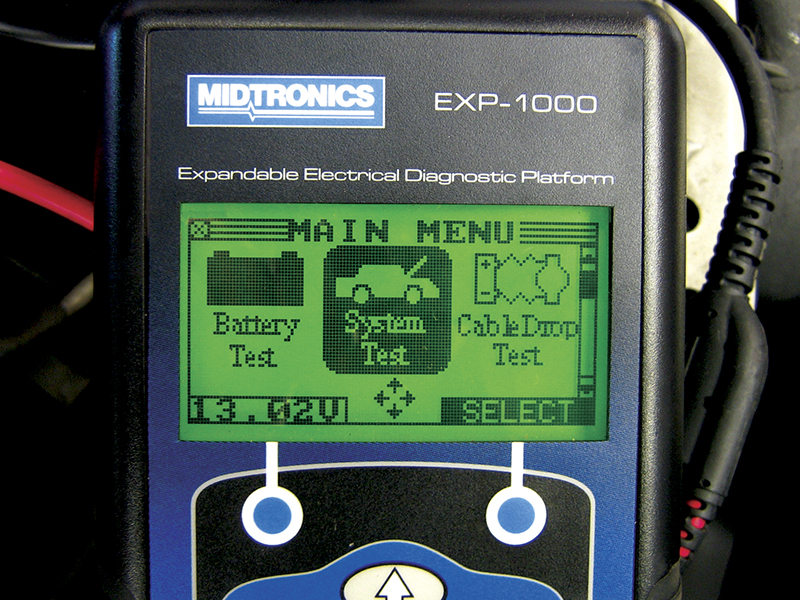
This may seem like a lot of extra work to do before starting a seemingly unrelated electronic diagnosis. The good news is that the new generation of conductance testers, such as the hand-held Midtronics EXP-1000, or the Midtronics GR-8 diagnostic station, are able to perform just such tests in less than five minutes, which makes checking the basics on every car a lot more attractive.
The old way: Testing the battery with a carbon-pile tester.
Testing the battery with an old-fashioned carbon-pile load tester can be accurate, but only if the test is done properly.
Before testing:
- Always be sure to check the electrolyte levels. If a plate is exposed, the battery may explode during load testing, assaulting you with flying plastic, acid spray, and a boom that may cause hearing loss.
- Test the state of charge. Unless the battery has rested for about six hours before the voltage measurement is taken, using a hydrometer or refractometer is a far more accurate way to test SOC (State of Charge) than open circuit voltage. After the proper rest, the open circuit voltage should be 12.45V (75% SOC), or higher, before load testing.
- If the battery is discharged, charge it properly. Charging voltage should not exceed 14.7V. Plan on a battery that is discharged to 11.89V or lower taking 10 to 16 hours (or more) to fully charge. A battery that is 12.24V will take about 5 hours to charge enough to test. The all-to-common practice of a 90-minute fast charge on “HI†will damage a battery with less than a 70% charge (12.40V), and if open circuit voltage is used as an indicator of SOC, the battery may undeservedly fail a subsequent load test.
Evaluate a battery load test as follows:
The voltage measured after 15 seconds with a load equal to ½ the battery’s CCA rating applied should be greater than or equal to 9.6V with an electrolyte temperature of 70 deg. F.
However, if the electrolyte temperature is not 70 deg. F, you must compensate with the following formula:
Add 0.1V for every 10 deg. over 70 deg. F, or subtract 0.1V for every 10 deg. under 70 deg. F.
The temperature compensation is often left out of load testing, even when the battery is tested after sitting out overnight or right after a test drive on a hot day. However, it’s necessary to include temperature compensation if accurate results are your goal.
Another pitfall when load testing: Recharging a battery just prior to a load test may temporarily mask a bad battery. A second load test may be a good idea if the battery required charging before the test.
The new way: Using the Midtronics System Test
As you can see, testing a battery properly with a load tester can be very time-consuming, especially if the battery needs to be charged before testing.
Testing the battery with a conductance tester has numerous advantages:
- The battery can be tested in discharged condition.
- A recent charge will not “fool†the tester into falsely reporting it as good.
- There is no danger of explosion during testing.
- The temperature correction is made automatically, so there’s no need for a chart or manual calculation.
- Test results are as accurate as load testing, when load testing is done properly, and more accurate than improper load testing.
- Tester algorithms are able to quickly find shorted cells.
- Electrolyte level should still be checked, but the battery won’t explode if this step is forgotten.
The Midtronics System Test performs a quick menu-guided series of checks. The entire procedure takes less than five minutes, and can be done with a small hand-held tester, so there’s no need to roll a cumbersome cart across the shop.
Many Midtronics testers are able to print a diagnostic report at the end of the system test. In fact, Nissan and Infiniti dealerships are required to submit a printout from the Midtronics GR-8 testing station for warranty claims on batteries, starters, and alternators as proof that proper testing was performed. Independent repair shop patrons will likely also appreciate documentation of problems with a manufacturer-approved testing system.
Hook it up
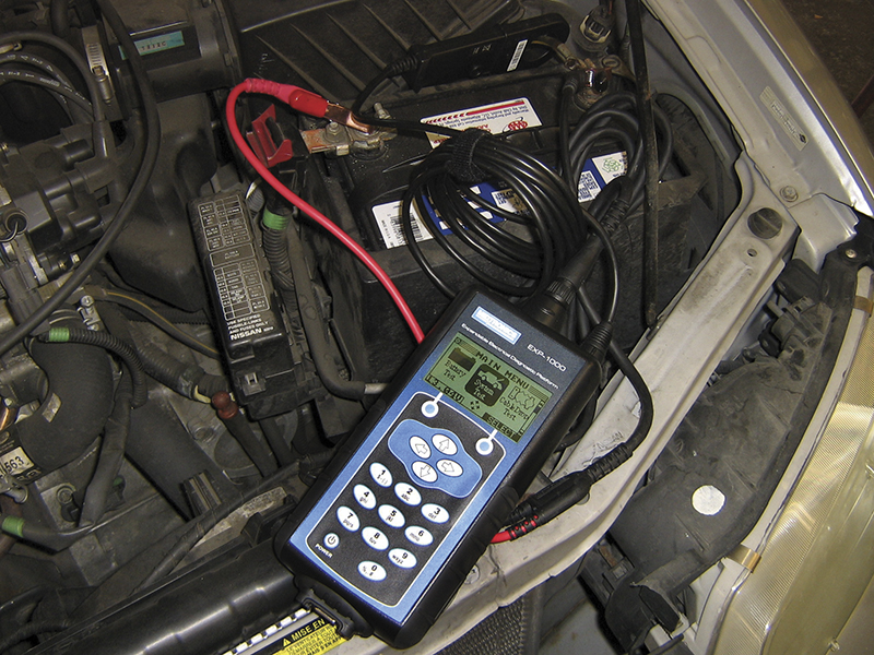
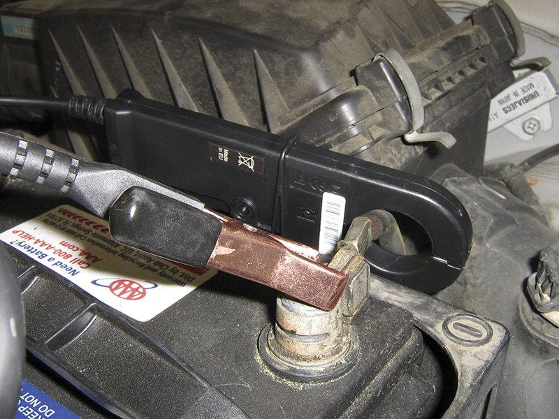
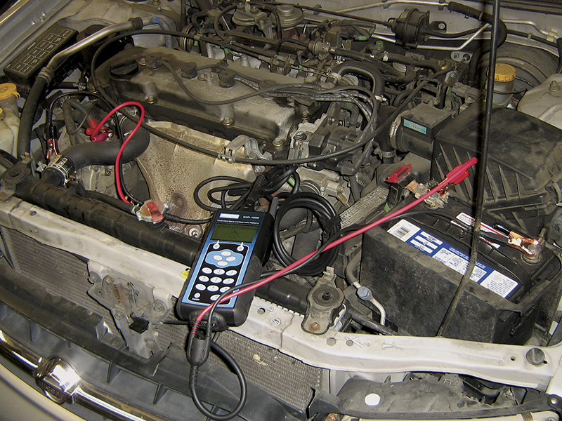
The Midtronics testers are easy to hook up. A system test can be performed with just the positive and negative probes clamped on the battery terminals. However, for more accurate testing, it’s also a good idea to connect the amp clamp.
With Midtronics testers, connecting the amp clamp is easy. It is simply placed around the negative battery cable (Figure 5). In contrast, conventional VAT testing requires the amp clamp be placed on the B+ cable at the back of the alternator, which can require a bit of contortion on some cars.
Test the battery
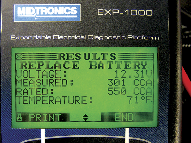
The Midtronics System Test begins with a battery check. The Midtronics tester uses conductance to determine the battery’s state of health and predict how long it might continue to function adequately. A small AC ripple is applied to the battery, which generates an AC response. The relative ratio of AC current variation to AC voltage variation is measured, and an algorithm is applied to the measurement to produce a Good/Bad/Marginal response, as well a CCA rating equivalent.
Understanding load testing is certainly more intuitive, but luckily we don’t need to fully understand how conductance testing works for it to work well for us. Just follow the on-screen prompts, and rest assured the results will be as accurate as a properly performed load test, just a whole lot faster.
Test the starting system
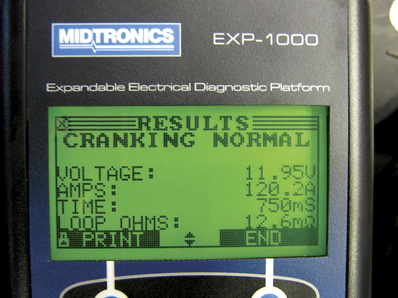
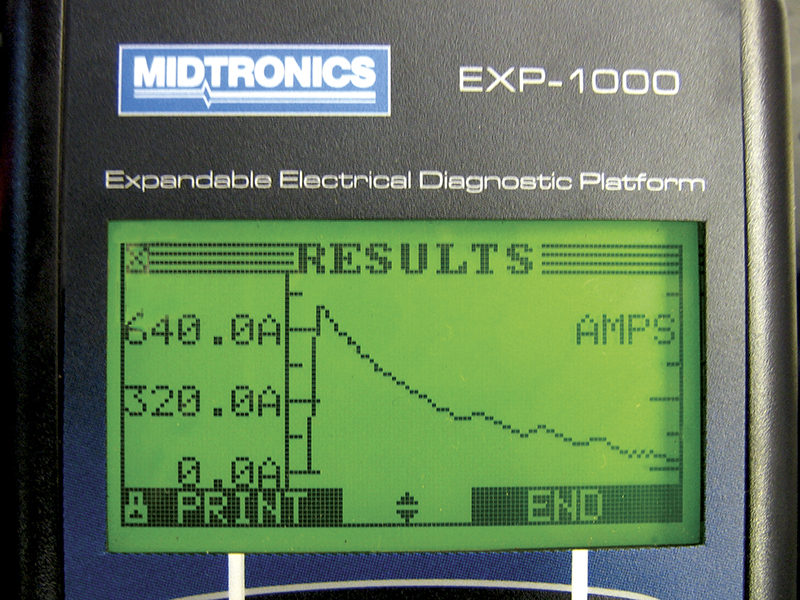
After the battery test is complete, the Midtronics unit prompts you to start the car while it monitors cranking voltage (Figure 7) and amperage (Figure 8). The tester’s sample rate is quite high – similar to an oscilloscope’s – so it’s able to measure, record, and graph spikes in both voltage and amperage in the short period of cranking before the engine starts up. This means the ignition or fuel systems don’t need to be disabled to test cranking voltage and starter draw, which saves time compared to standard starter testing with an amp clamp and voltmeter.
Once the engine starts, the tester reports any starting system problems. If the battery is discharged or bad, the tester will remind you of this instead of displaying the starter test results, so the starting system test will need to be performed again after the battery has been recharged or replaced. The starting system test takes only a few seconds, but provides very accurate results.
Test the charging system
In the charging system test, the tester takes measurements during four phases:
- 2,000 rpm with accessories off for five seconds
- idle with accessories off for five seconds
- idle with high beams, blower, and rear defroster on for five seconds
- 2,000 rpm with high beams, blower, and defroster on for five seconds
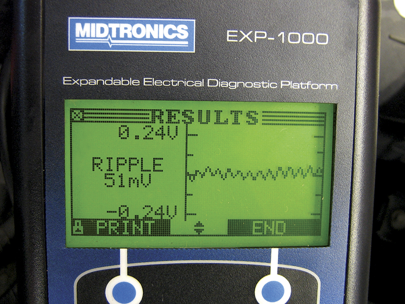
This 20-second test yields a wealth of information. The Midtronics tester determines the health of the diodes, checks for an open or shorted stator phase, and verifies adequate alternator output.
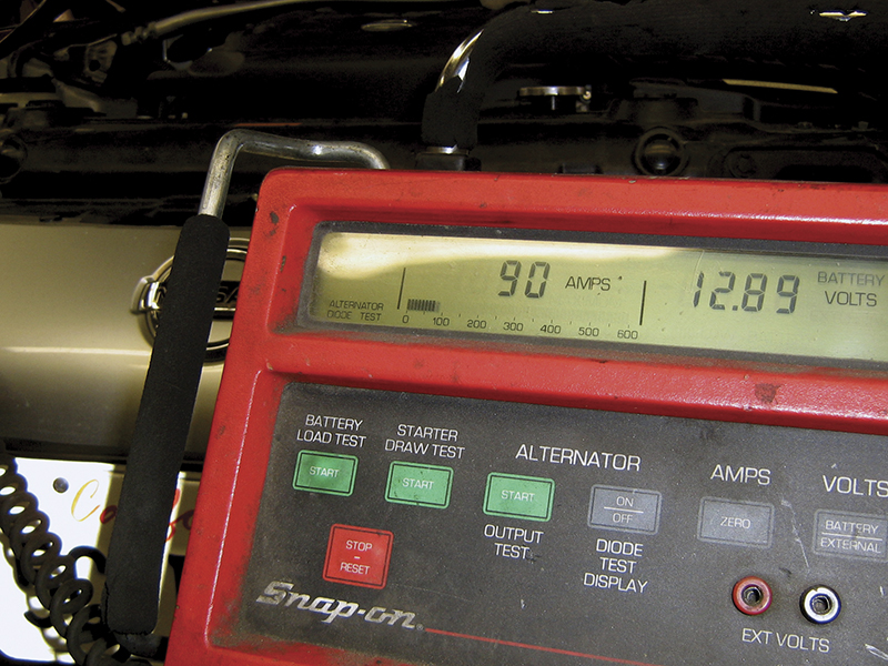
Although it’s no longer the officially recommended Nissan tool, a carbon pile tester (Figure 10) can still be useful to test alternator output beyond what accessory load will pull. So even though the Midtronics tester will nearly always be the best choice, don’t roll the VAT-40 out to the curb yet. It may still come in handy in a few cases.
The results of the five-minute test
- You know whether the vehicle’s power supply system is working.
- You know whether the electronic components have adequate power when the starter load is pulling the system voltage down.
- You know whether running volt age is too high or contaminated with AC ripples.
In short, you know whether an inadequate power supply might be the cause of your troubles, or whether you should continue with the normal diagnostic procedure. If the reason for the test was a check of the basics, you’re done.
However, starting and charging system inspection can also be used for the more traditional reason – finding problems that might prevent the vehicle from starting. Now that the System Test is complete, you know if the battery has the necessary capacity to start the car reliably. You know if the alternator is able to power the car and recharge the battery. You know whether or not the starter is getting the power it needs to crank the engine.
There are a few more things that need to be tested if the customer concern is a no-start condition.
Test for key off drain
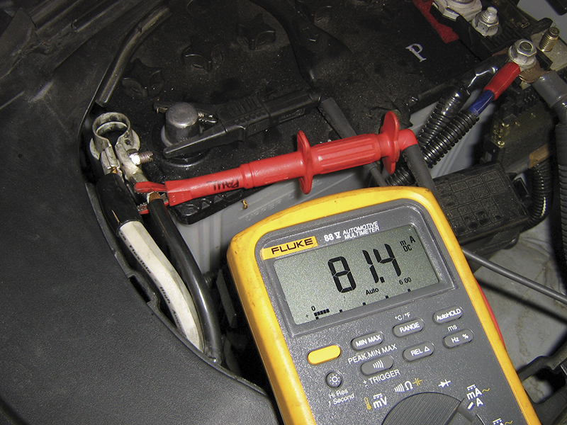
Key-off drain should be checked to ensure the battery is not going to discharge while the vehicle isn’t in use. The best tool for this job is an ammeter capable of accurately measuring current in milliamps. Simply hook the leads in series with the negative cable by disconnecting the negative cable from the battery post, then attaching one meter lead to the negative battery cable and the other to the negative battery post (Figure 11).
The level of acceptable drain varies depending on the battery’s capacity and the length of time the car’s likely to be sitting unused, but as a general rule, key-off drain should be less than 80 mA, and is usually much lower.
When testing for key-off drain, it’s important to remember that control units normally stay active for a while, or even become active at certain times. A draw of 400 mA, or even 800 mA, may be normal, so long as it doesn’t last too long. One method of differentiating battery-draining draws from normal momentary draws is to use the MIN/MAX feature built in to many DVOMs. The average draw can be found by recording the key-off drain over a period of time then deciding if it’s acceptable.
Test for voltage drops
If the System Test finds a problem with the starter or alternator circuit, voltage drop testing may be necessary. In a nutshell, voltage drop testing is measuring how much voltage a given segment of a circuit is consuming. In starting and charging system testing, the focus is usually on the battery cables and the alternator B+ cable.
By using conductance technology, Midtronics testers provide a new and timesaving way to perform voltage drop testing without even operating the load. The tester comes with two sets of leads, the standard leads used for battery testing, and an additional set for DMM and scope testing. By connecting both sets, one at the component and the other at the battery, both sides of the circuit can be tested at the same time.
For testing the starter circuit:
- Select STARTER CIRCUIT.
- Select the circuit rating (150A is the default, but the tester can test circuits with ratings up to 1000A).
- Connect battery probes to the starter: B+ to the starter’s battery stud, B- to the starter housing.
- Connect the DMM probes to the battery:Â positive probe to positive terminal, negative probe to negative terminal.
- Wait for the test to complete and read the results.
There’s no need to crank the engine, disable the ignition, or test one side of the circuit at a time. The results are displayed in voltage drop for both sides individually. There’s no need to memorize the maximum allowable voltage drop for a given circuit; the tester will alert the user to any problems.
In addition to the starter circuit test, the Midtronics tester also has preset tests for the voltage drop on the alternator circuit and the battery body ground strap. Beyond that, any circuit can be voltage-drop tested by selecting OTHER, then manually entering the amperage rating.
Wrap up
In the past, battery, starting and charging system diagnosis was most often performed because a car either wouldn’t start, or died while driving. On today’s Nissan and Infiniti cars, these systems’ critical responsibilities go far beyond providing power for the starter and ignition system. Digital communication’s role will only increase with every new model year. Quickly verifying a good power supply will be key to avoiding unnecessary diagnostic difficulties. So, whether you’re diagnosing a warning light or a power window, start with the basics — verify a good power supply. You’ll be glad you did!



0 Comments